Tip turbine engine with reverse core airflow

a technology of reverse core airflow and turbine engine, which is applied in the direction of machines/engines, stators, liquid fuel engines, etc., can solve the problems of increasing reducing the overall length and weight of the engine, and reducing the overall weight of the engin

Active Publication Date: 2012-05-10
RTX CORP
View PDF6 Cites 5 Cited by
  • Summary
  • Abstract
  • Description
  • Claims
  • Application Information

AI Technical Summary

Benefits of technology

[0007]A tip turbine engine according to the present invention provides increased efficiency while eliminating or reducing the number of axial compressor stages by moving the core airflow inlet aft of the fan. As a result, the core airflow entering the core airflow inlet is the fan exhaust, which is already compressed by the fan. The fan exhaust is fed axially forward and then radially outward through compressor chambers in the hollow fan blades for further, centrifugal compression.
[0009]In one embodiment, the fan of the tip turbine engine drives the axial compressor via at least one gear that increases the rate of rotation of the axial compressor relative to the fan and / or reverses the direction of rotation of the axial compressor relative to the fan.

Problems solved by technology

The axial flow relationship results in a relatively complicated elongated engine structure of considerable longitudinal length relative to the engine diameter.
This elongated shape may complicate or prevent packaging of the engine into particular applications.
Increasing the number of stages of compressor blades increases the compression of the core airflow and the efficiency of the engine, but increases the overall length and weight of the engine and the number of parts.

Method used


Image

  • Tip turbine engine with reverse core airflow
  • Tip turbine engine with reverse core airflow
  • Tip turbine engine with reverse core airflow

Examples


Embodiment Construction

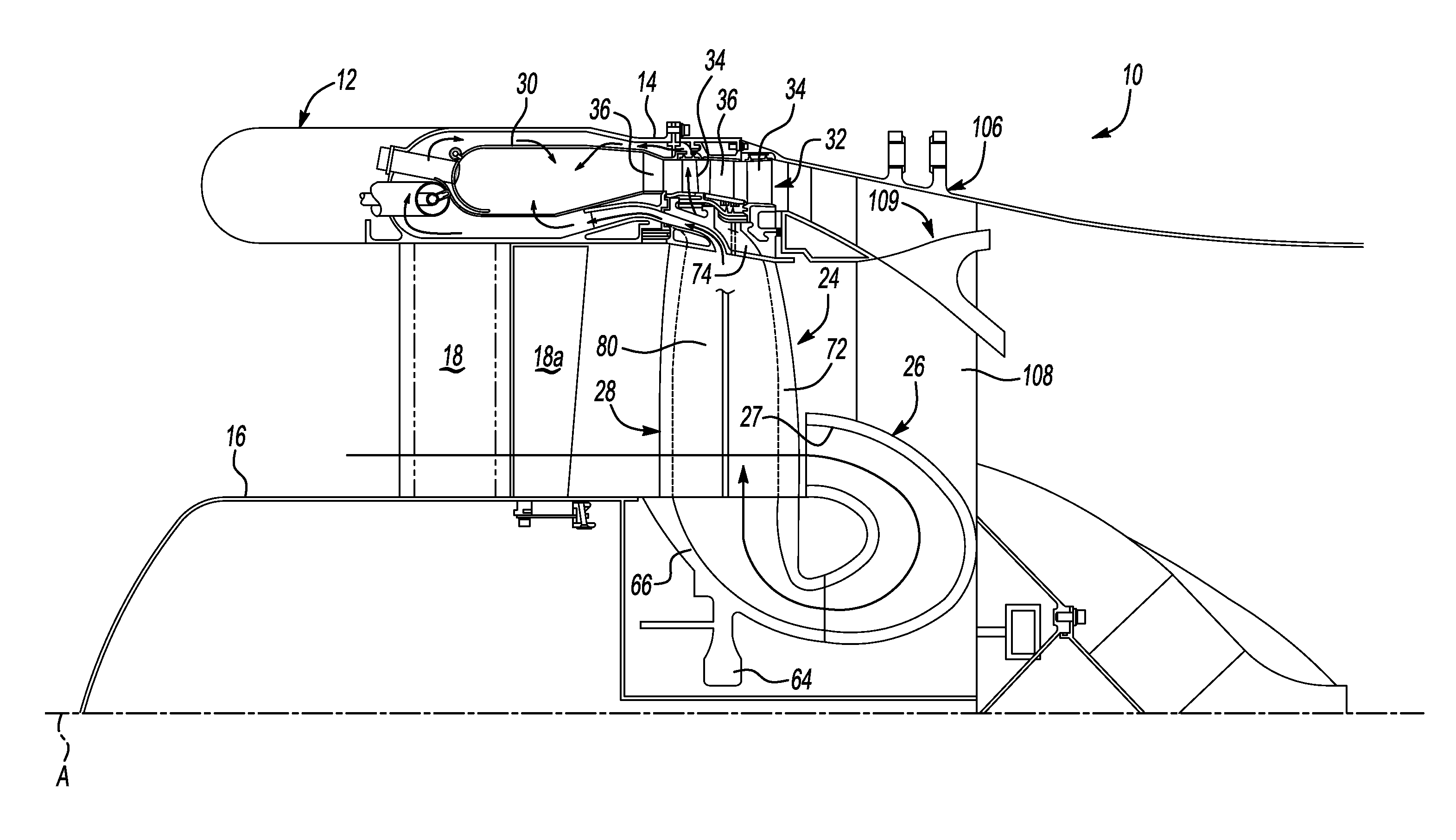
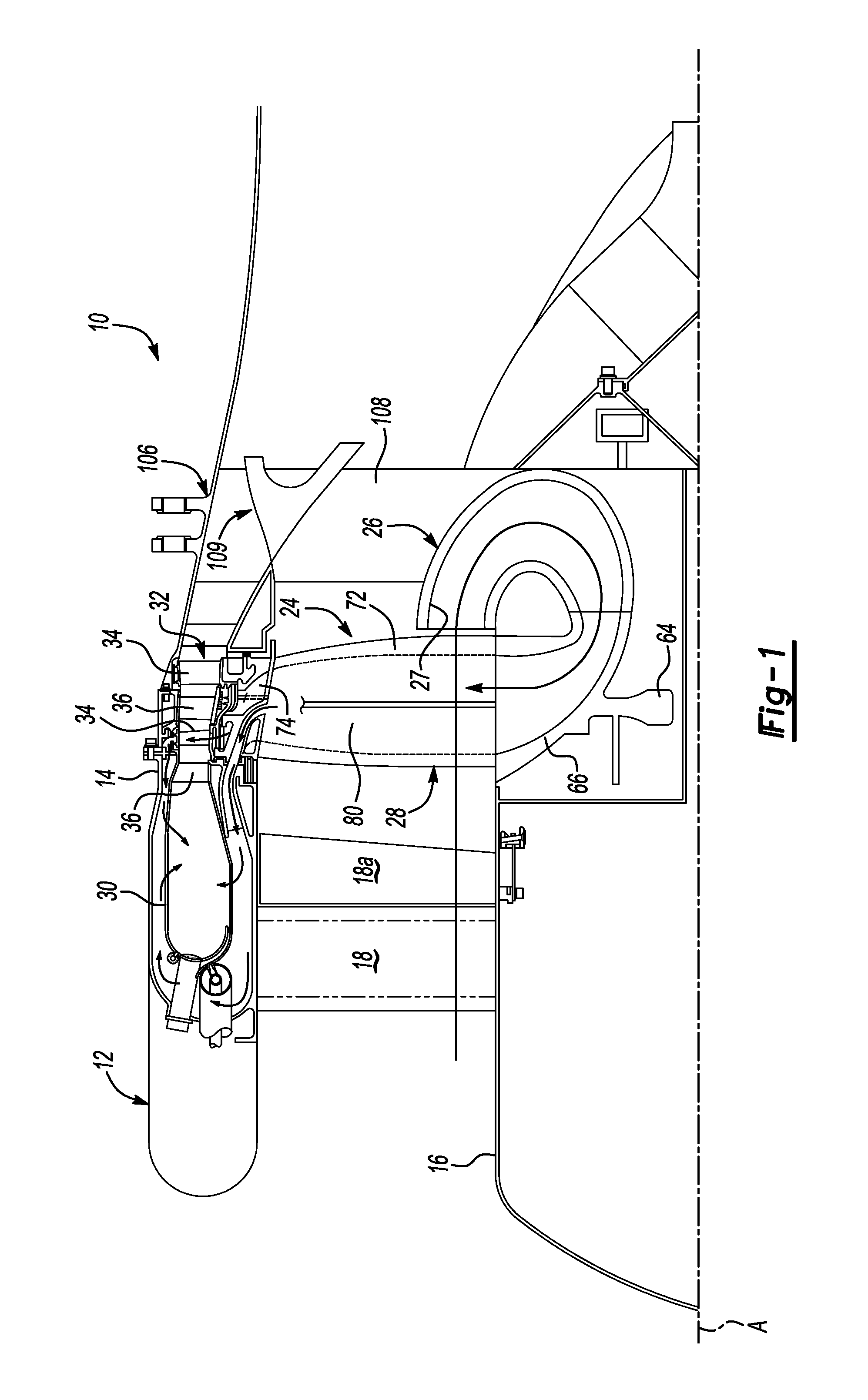
[0014]FIG. 1 illustrates a partial sectional view of a tip turbine engine (TTE) type gas turbine engine 10 taken along an engine centerline A. The engine 10 includes an outer nacelle 12, a rotationally fixed static outer support structure 14 and a rotationally fixed static inner support structure 16. A plurality of fan inlet guide vanes 18 are mounted between the static outer support structure 14 and the static inner support structure 16. Each inlet guide vane preferably includes a variable trailing edge 18a.

[0015]A fan-turbine rotor assembly 24 is mounted for rotation about the engine centerline A fore of a core airflow passage 26 having a core airflow inlet 27. The fan-turbine rotor assembly 24 includes a plurality of hollow fan blades 28 to provide internal, centrifugal compression of the compressed airflow for distribution to an annular combustor 30 located within the rotationally fixed static outer support structure 14. The core airflow inlet 27 is aft of the fan blades 28 and...


PUM


Abstract

A tip turbine engine provides increased efficiency while eliminating or reducing the number of axial compressor stages by moving the core airflow inlet aft of the fan. As a result, the core airflow entering the core airflow inlet is the fan exhaust, which is already at an increased pressure. A portion of the fan exhaust is guided radially inward, then axially forward and then radially outward through compressor chambers in the hollow fan blades for further, centrifugal compression.

Description

[0001]This application is a continuation of U.S. application Ser. No. 11 / 719,587 filed on May 17, 2007, which is a National Phase of PCT Application No. PCT / US2004 / 040067 filed on Dec. 1, 2004.BACKGROUND OF THE INVENTION[0002]The present invention relates to a tip turbine engine, and more particularly to a tip turbine engine with a core airflow inlet aft of a bypass fan.[0003]An aircraft gas turbine engine of the conventional turbofan type generally includes a forward bypass fan, a low pressure compressor, a high pressure compressor, a combustor, a high pressure turbine, and a low pressure turbine, all located along a common longitudinal axis. The low and high pressure compressors are rotatably driven to compress entering air to a relatively high pressure. This high pressure air is then mixed with fuel in the combustor, where it is ignited to form a high energy gas stream. This gas stream flows axially aft to rotatably drive the high pressure turbine, which rotatably drives the high...

Claims


Application Information

Patent Timeline
Patent Type & Authority Applications(United States)
IPC IPC(8): F02C3/04F01D1/04
CPCF01D5/022F02C3/064F02C3/073F05D2260/40311F02K3/025F02K3/068F04D25/045F02C7/36
Inventor NORRIS, JAMES W.NORDEEN, CRAIG A.
Owner RTX CORP
Why Eureka
Try Eureka