Carbon Dioxide Removal Process

a carbon dioxide and process technology, applied in the separation process, membranes, lighting and heating apparatus, etc., can solve the problems of increased separation process costs and additional high costs, and achieve the effect of minimizing the loss of hydrocarbons

Active Publication Date: 2012-05-10
LAIR LIQUIDE SA POUR LETUDE & LEXPLOITATION DES PROCEDES GEORGES CLAUDE
View PDF3 Cites 74 Cited by
  • Summary
  • Abstract
  • Description
  • Claims
  • Application Information

AI Technical Summary

Benefits of technology

[0010]The present invention provides a process for treating a hydrocarbon containing feed stream which minimizes the loss of hydrocarbons while at the same time allowing for the recovery of a high pressure carbon dioxide stream. The process involves utilizing a membrane separation unit in conjunction with a h...

Problems solved by technology

However, while the hydrocarbon losses are decreased by using such processes, there is an increase in the separation process costs.
Furthermore, the carbon dioxide that is vented in such processes is typically obtained at low pressure...

Method used


Image

  • Carbon Dioxide Removal Process
  • Carbon Dioxide Removal Process
  • Carbon Dioxide Removal Process

Examples


first embodiment

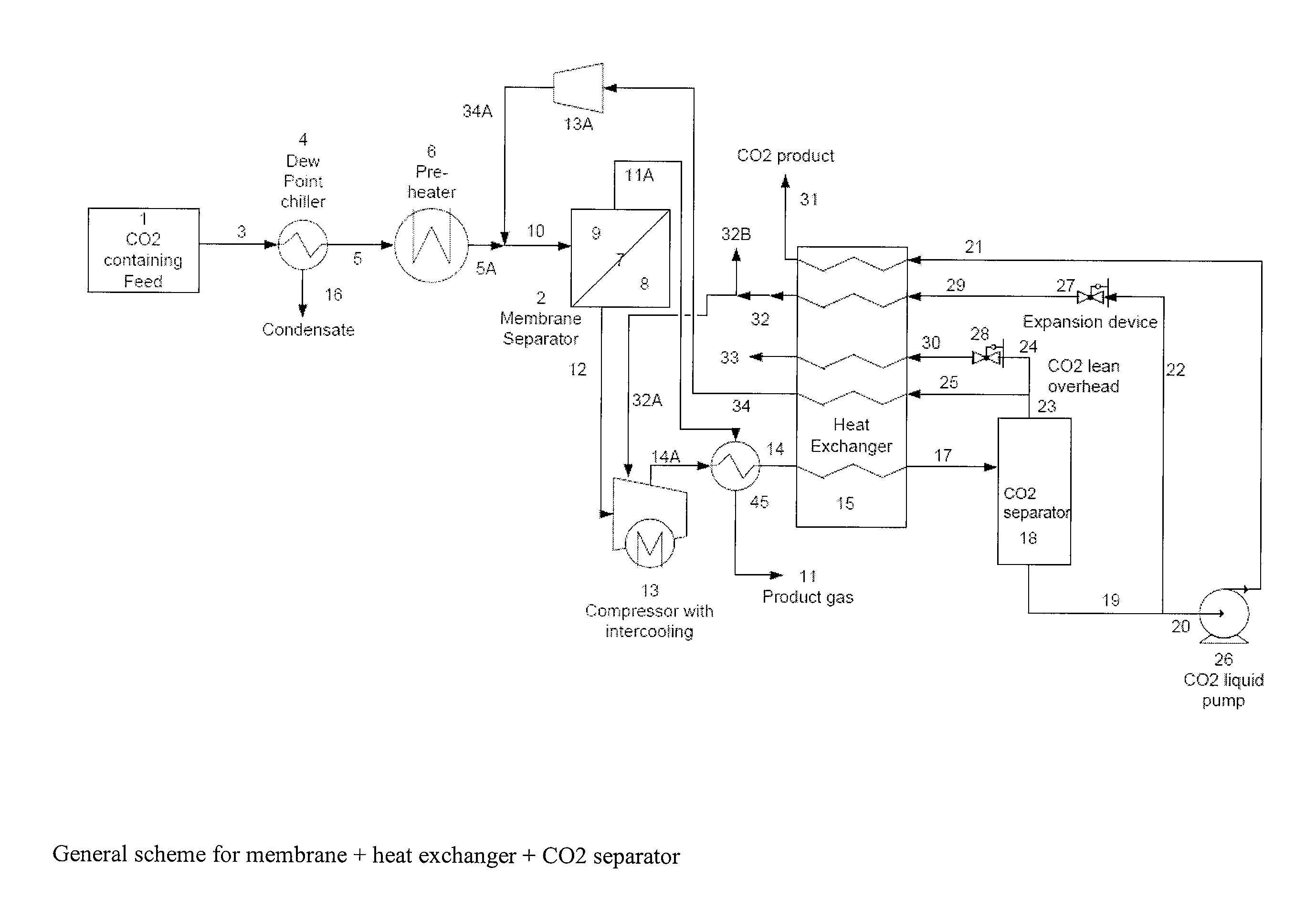
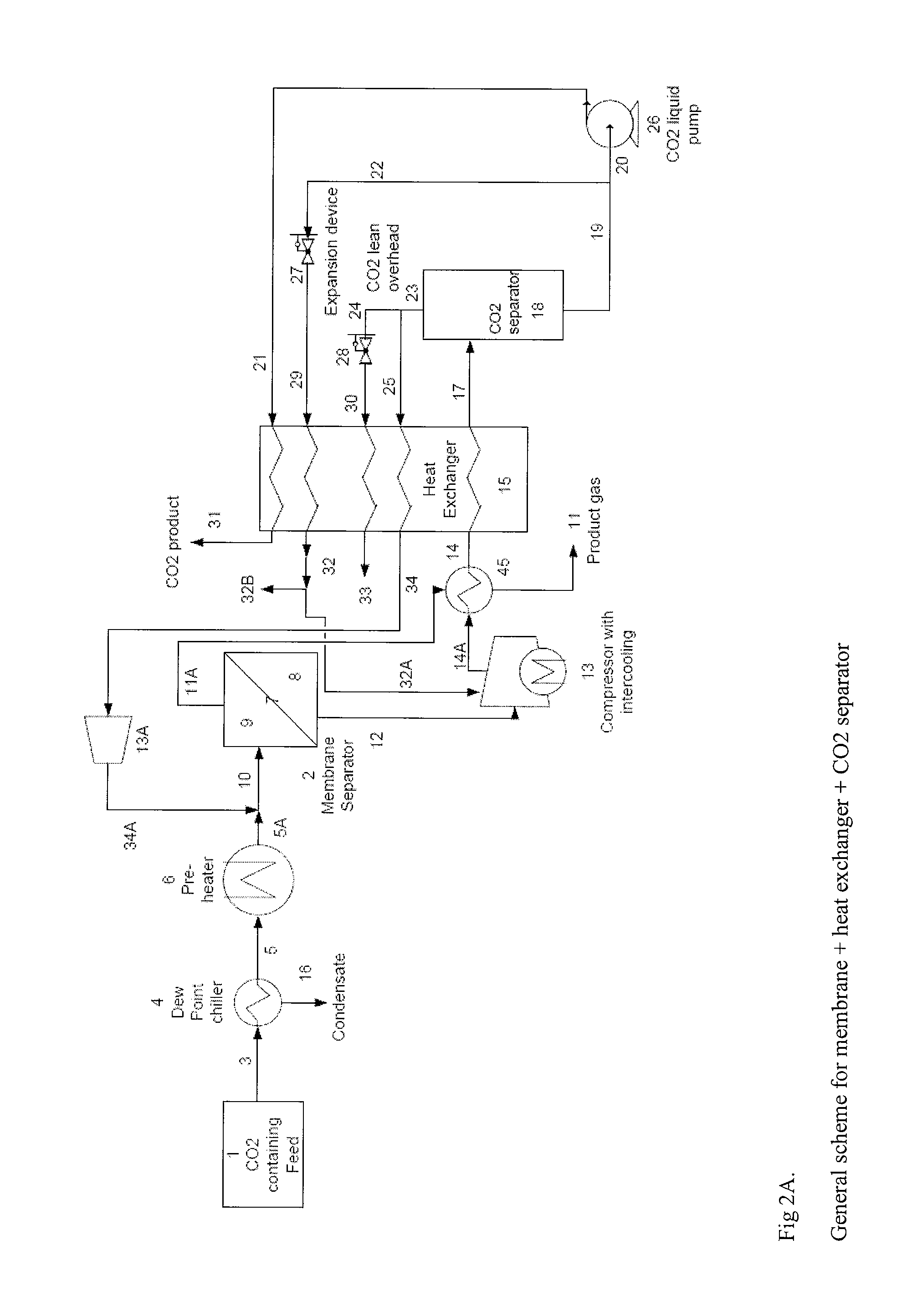
[0021]The present process will be further described with reference to FIGS. 2 to 6 of the present invention as provided herein. These figures, while setting forth specific embodiments of the present process, are not meant to be limiting. There are two main embodiments of the present invention, each with a number of sub-embodiments. More specifically, the present invention as set forth in FIG. 2A, provides for a process for recovering carbon dioxide from a hydrocarbon containing feed stream utilizing a membrane separation unit to form a first membrane stream and a second membrane stream; withdrawing the second membrane stream for further use; compressing the first membrane stream in a compressor followed by cooling in a heat exchanger; separating and purifying the compressed, cooled first membrane stream in a carbon dioxide separation unit to produce a carbon dioxide rich liquid stream and a carbon dioxide lean vapor stream; and then utilizing these two streams to provide the source ...

second embodiment

[0022]the present invention, as set forth in FIG. 3A, provides for a process for recovering carbon dioxide from a hydrocarbon containing feed stream utilizing a primary membrane separation unit to form a first membrane stream and a second membrane stream; withdrawing the second membrane stream for further use; compressing the first membrane stream in a compressor followed by cooling in a heat exchanger; separating and purifying the compressed, cooled first membrane stream in a carbon dioxide separation unit to produce a carbon dioxide rich liquid stream and a carbon dioxide lean vapor stream; and then utilizing these two streams to provide the source of cooling in the heat exchanger for the compressed first membrane stream with the carbon dioxide rich liquid stream either being sent directly to the heat exchanger or as an option being split into two fractions with one of the fractions being subjected to expansion prior to being sent to the heat exchanger in order to provide further ...


PUM

PropertyMeasurementUnit
Temperatureaaaaaaaaaa

Abstract

A process for efficiently removing carbon dioxide from a hydrocarbon containing feed stream utilizing a membrane separation unit in conjunction with a heat exchanger and a carbon dioxide separation unit wherein the streams obtained in the carbon dioxide separation unit are utilized to provide the cooling effect in the heat exchanger.

Description

CROSS-REFERENCE TO RELATED APPLICATIONS[0001]This is a Non-Provisional of U.S. Provisional Patent Application No. 61 / 390,399 filed Oct. 6, 2010, entitled CARBON DIOXIDE REMOVAL PROCESS.FIELD OF THE INVENTION[0002]The present invention relates to a process for efficiently removing carbon dioxide from a hydrocarbon containing feed stream utilizing a membrane separation unit in conjunction with a heat exchanger and a carbon dioxide separation unit wherein the streams obtained in the carbon dioxide separation unit are utilized to provide the cooling effect in the heat exchanger.BACKGROUND OF THE INVENTION[0003]Membranes have been used to remove carbon dioxide and other acid / polar gases from natural gas. Membrane processes have been used to serve as a bulk cut separation of carbon dioxide. In such processes the carbon dioxide permeates through the membrane thereby giving rise to a carbon dioxide enriched permeate gas which is vented at low pressure and a hydrocarbon (HC) enriched product...

Claims


Application Information

Patent Timeline
IPC IPC(8): F25J3/08F25J3/02F25J3/00
CPCB01D53/1475Y02C10/06B01D53/229B01D71/64B01D2257/504B01D2311/04B01D2311/06B01D2311/08B01D2311/103B01D2311/106B01D2311/13B01D2311/25B01D2311/2669B01D2311/2673B01D2317/022F25J3/0209F25J3/0233F25J3/0266F25J3/029F25J3/061F25J3/0635F25J3/067F25J3/069F25J2200/02F25J2200/30F25J2205/04F25J2205/40F25J2205/80F25J2210/04F25J2215/04F25J2220/82F25J2230/30F25J2235/80F25J2245/02Y02C10/10Y02C10/12B01D53/226Y10S62/928Y02E50/346C10L3/104Y02C20/40Y02E50/30
Inventor KULKARNI, SUDHIR S.SANDERS, JR., EDGAR S.
Owner LAIR LIQUIDE SA POUR LETUDE & LEXPLOITATION DES PROCEDES GEORGES CLAUDE
Why Eureka
Try Eureka