Helical coil steam generator

a technology of steam generators and coils, applied in steam boilers, steam generation plants, lighting and heating apparatus, etc., can solve problems such as the weakened state of tube walls

Active Publication Date: 2012-05-10
NUSCALE
View PDF15 Cites 20 Cited by
  • Summary
  • Abstract
  • Description
  • Claims
  • Application Information

AI Technical Summary

Benefits of technology

[0019]A steam generator is herein disclosed as comprising a lower integral tubesheet / plenum (ITP) configured to receive feedwater and a first set of heat transfer tubes fluidly coupled to a plurality of stubs protruding from a first side of the lower ITP. A second set of heat transfer tubes fluidly couples to plurality of stubs protruding from a second side of the lower ITP. The first set of heat transfer tubes is coiled in a substantially clockwise direction, and the second set of heat transfer tubes is coiled in a substantially counter-clockwise direction. The steam generator further includes one or more upper ITP fluidly coupled to the first and second set of heat transfer tubes, wherein the feedwater entering the lower ITP is converted to steam in the first and second sets of heat transfer tubes. The one or more upper ITPs are configured to transport the steam away from the steam generator.
[0020]Two or more independent tube bundles may be used to provide for redundant and independent steam generator operations. Feedwater and steam flows may be independently controlled to the independent bundles to allow for continued operation in the event of a failure of one of the steam generator bundles.
[0021]An apparatus is herein disclosed as comprising a means for receiving a source of feedwater and a means for fluidly coupling the means for receiving to a first set of heat transfer tubes coiled about a heat source in a first direction of rotation. The first tube bundle is configured to convert the feedwater into steam. The apparatus includes a means for fluidly coupling the means for receiving to a second set of heat transfer tubes coiled about the heat source in a second direction of rotation, wherein the first and second sets of heat transfer tubes comprise a plurality of tubes that cross over each other in alternating directions. The means for transporting the steam away from the heat source is fluidly coupled to the first and second sets of heat transfer tubes via a plurality of stubs protruding from one or more ITPs. The sets of tubes associated with a given ITP may constitute a bundle of heat transfer tubes for a steam generator.

Problems solved by technology

However, by expanding the tubes, this causes a plastic deformation that leads to a weakened state of the tube wall and serves as a potential point of failure.

Method used


Image

  • Helical coil steam generator
  • Helical coil steam generator
  • Helical coil steam generator

Examples


Embodiment Construction

[0024]Various embodiments disclosed or referred to herein may be operated consistent, or in conjunction, with features found in co-pending U.S. application Ser. No. 11 / 941,024 which is herein incorporated by reference in its entirety.

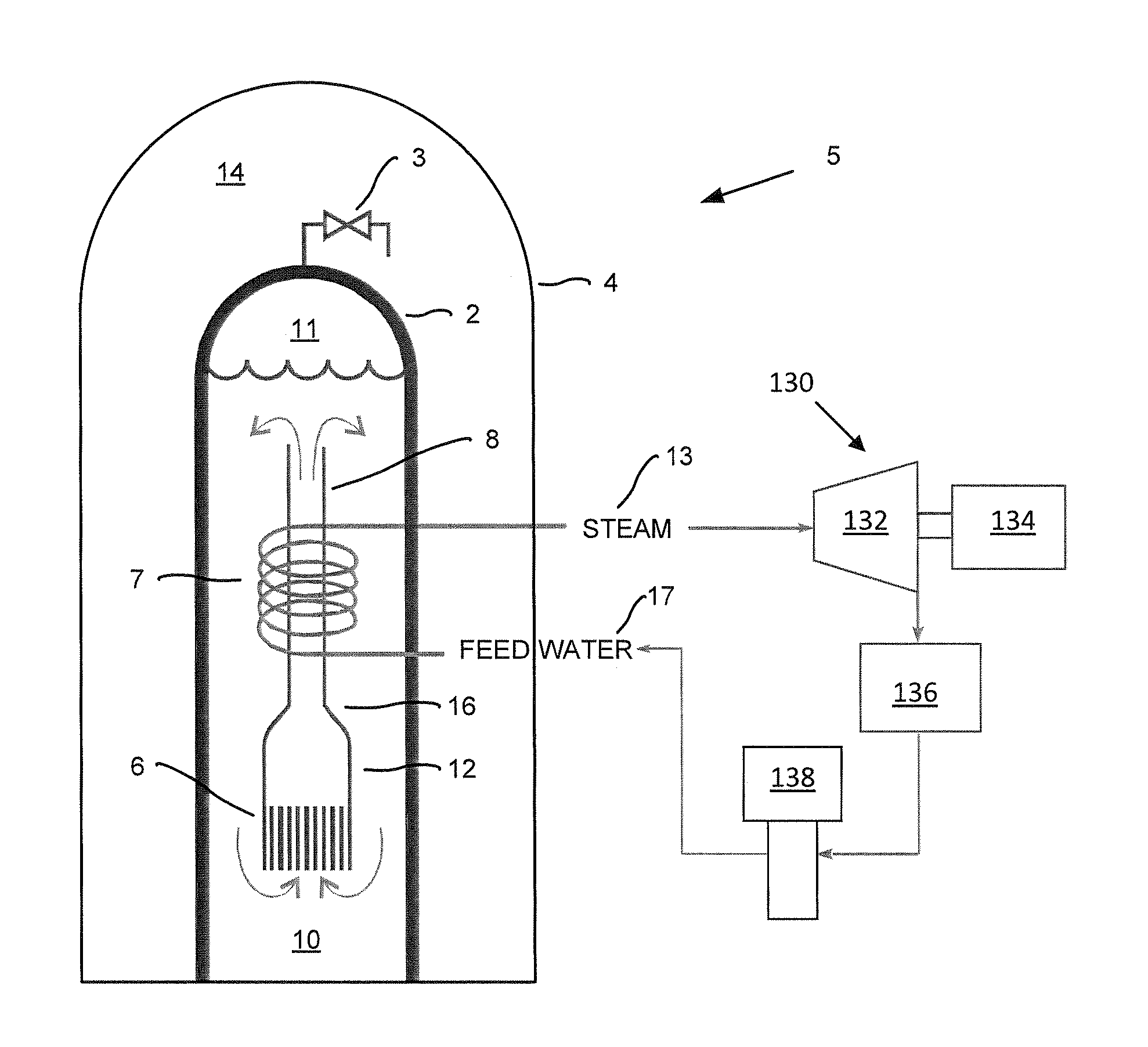
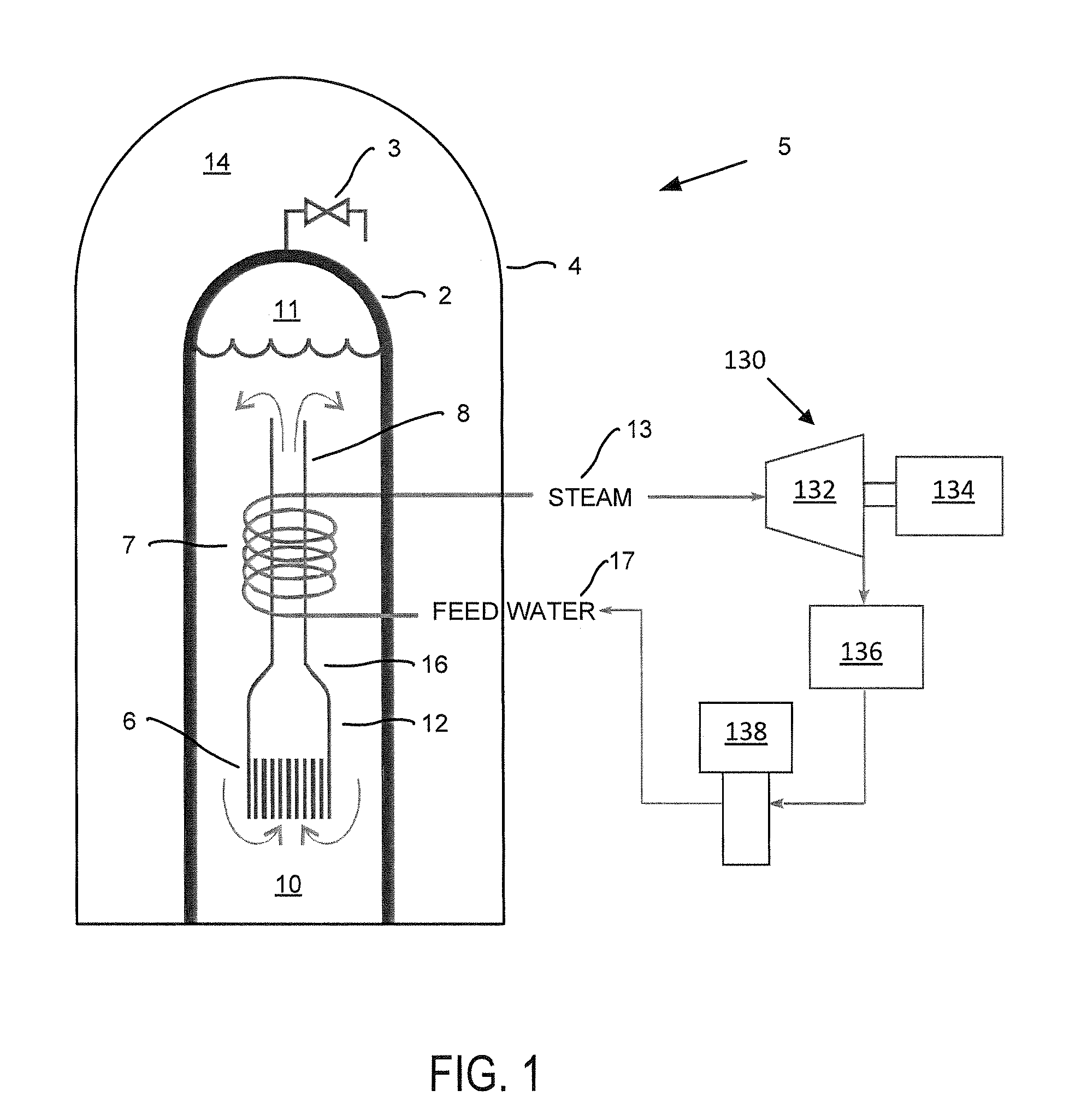
[0025]FIG. 1 illustrates an example nuclear power system 5 including a secondary cooling system 130. A reactor core 6 is surrounded by a reactor vessel 2. Primary coolant 10, such as water or sodium, in the reactor vessel 2 surrounds the reactor core 6. The reactor core 6 is further located in a shroud 12 which surrounds the reactor core 6 about its sides. When the primary coolant 10 is heated by the reactor core 6 as a result of fission events, the primary coolant 10 is directed from the shroud 12 and out of a riser 8. This results in further primary coolant 10 being drawn into and heated by the reactor core 6 which draws yet more primary coolant 10 into the shroud 12. The water 10 that is transmitted through the riser 8 is cooled down by a heat exchan...


PUM

PropertyMeasurementUnit
heightaaaaaaaaaa
inner radiusaaaaaaaaaa
angleaaaaaaaaaa

Abstract

A steam generator includes a lower integrated tubesheet and plenum (ITP) configured to receive feedwater and a first set of heat transfer tubes fluidly coupled to a plurality of stubs protruding from a first side of the lower ITP. A second set of heat transfer tubes fluidly couples to plurality of stubs protruding from a second side of the lower ITP. The first set of heat transfer tubes is coiled in a substantially clock-wise direction, and the second set of heat transfer tubes is coiled in a substantially counter-clockwise direction. The steam generator further includes an upper ITP fluidly coupled to the first and second set of heat transfer tubes, wherein the feedwater entering the lower ITP is converted to steam in the first and second sets of heat transfer tubes. The upper ITP is configured to transport the steam away from the steam generator.

Description

TECHNICAL FIELD[0001]The invention relates to the field of power generation, including systems designed to generate steam.BACKGROUND[0002]Power plants come in many different shapes and sizes. Large power plants can be used to provide electricity to a geographic area, whereas relatively small power plants can be used to power local areas or submarines or space craft, for example. In addition to providing electricity, power plants can be used for a myriad of additional or different purposes, from desalinating sea water to creating nuclear isotopes for medical purposes. Similarly, the types of power plants that are available cover a wide spectrum of technologies including gas powered, coal fired, and various types of nuclear power, to name a few.[0003]One common feature between many of these power plants is the production of energy in the form of heat. Typically, the heat that is produced is ultimately used to convert water into steam. When the production of electricity is the desired ...

Claims


Application Information

Patent Timeline
Patent Type & Authority Applications(United States)
IPC IPC(8): F22B33/00B21D53/06
CPCF22B29/064F22B37/104F22B37/205Y10T29/49364B21D53/02F22B1/023Y10T29/49362F22B37/74B21D53/08B23P15/26
Inventor WILLIAMS, DENNIS KEITHFASSETT, DOUGLAS PAULWEBB, BRENT J.BEES, WILLIAM J.KRUSKAMP, ALEX SCOTT
Owner NUSCALE
Why Eureka
Try Eureka