Method for Delivering Fluids Using a Centrifugal Pump

a centrifugal pump and fluid technology, applied in the direction of non-positive displacement pumps, gas/liquid distribution and storage, liquid fuel engines, etc., can solve the problems of high energy consumption of compression and cooling, severe damage, and the pump may not be able to achieve the supercritical sta

Active Publication Date: 2012-05-10
KSB AG
View PDF8 Cites 6 Cited by
  • Summary
  • Abstract
  • Description
  • Claims
  • Application Information

AI Technical Summary

Benefits of technology

[0010]The object of the present invention is to provide a method which makes it possible to convey supercritical fluids by

Problems solved by technology

Both compression and cooling are highly energy-intensive.
Otherwise, the formation of vapor bubbles occurs, which implode in the event of overpressurizing the pump and lead to severe damage.
When liquid carbon dioxide is being conveyed, an unavoidable change to a supercritical state may occur

Method used


Image

  • Method for Delivering Fluids Using a Centrifugal Pump
  • Method for Delivering Fluids Using a Centrifugal Pump
  • Method for Delivering Fluids Using a Centrifugal Pump

Examples


Embodiment Construction

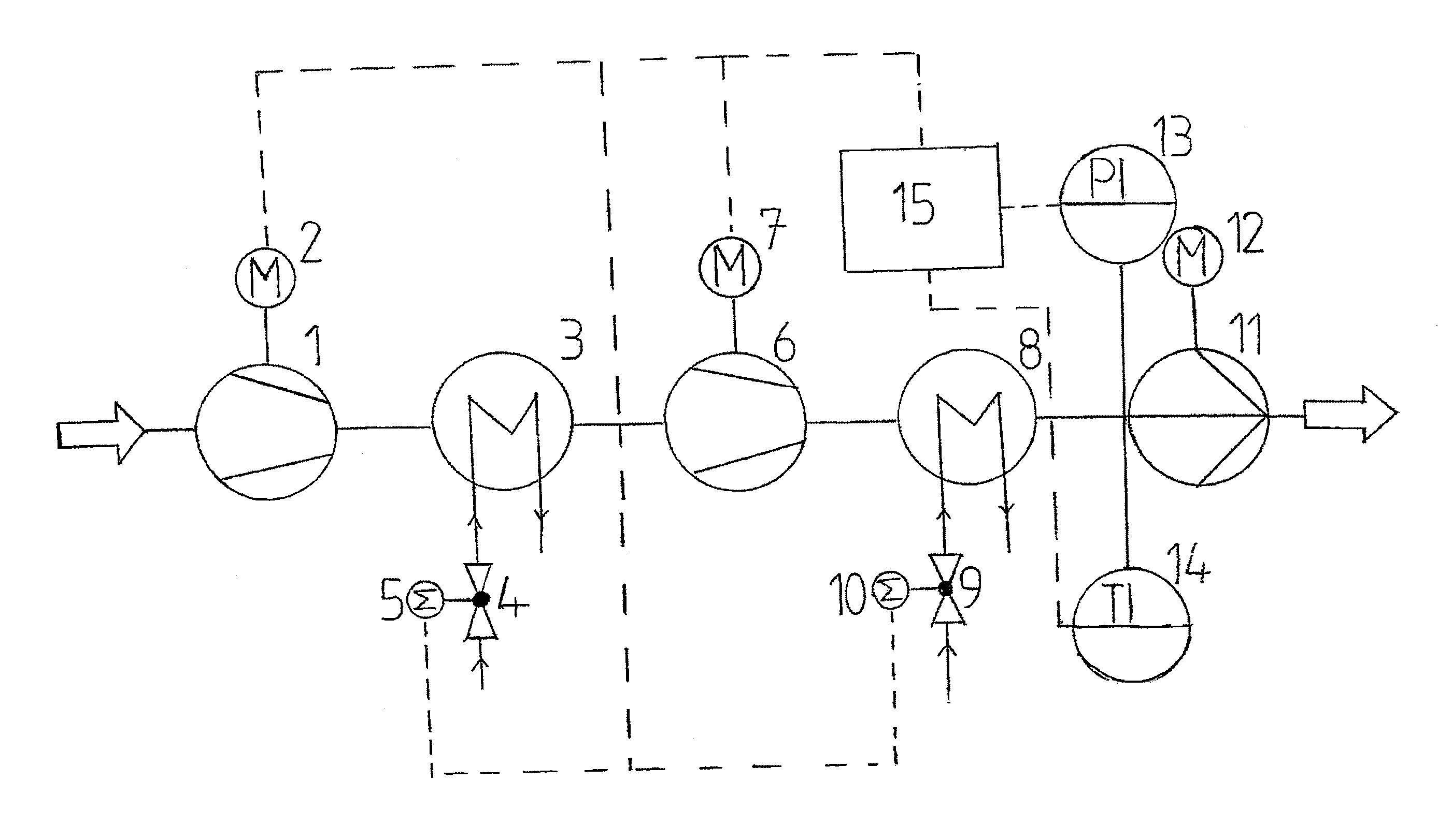
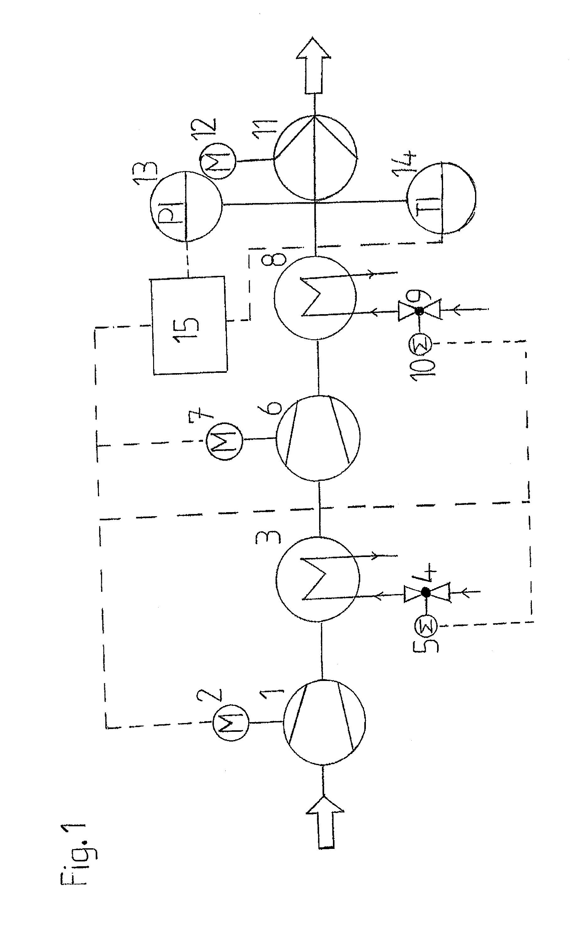
[0029]FIG. 1 shows a flow chart of the method according to the invention as a diagrammatic illustration. The fluid, which in this case is carbon dioxide, first enters a compressor 1. The compressor 1 is driven by a motor 2. This diagrammatic illustration applies to single-stage or multistage compressor forms of construction. The number of compressor and heat exchanger stages varies as a function of the state of entry of the fluid and coolant in the process illustrated. For the sake of clarity, only 2 process stages are illustrated here; however, there are usually several.

[0030]In the compressor 1, the fluid is brought to a higher pressure, the temperature of the fluid rising. Downstream of the compressor 1, the fluid enters a heat exchanger 3. The heat exchanger 3 through which coolant flows absorbs heat from the fluid stream and consequently lowers the temperature of the fluid. The coolant quantity is set by using a valve 4. As its actuating drive, the valve 4 is operated by a moto...


PUM


Abstract

A method for delivering a fluid using a centrifugal pump (11). Machines (1, 6) and/or apparatus (3, 8), which influence the pressure and/or the temperature of the fluid, are disposed upstream of the centrifugal pump (11). At the inlet to the centrifugal pump (11), the fluid is regulated to achieve a specific entry state. According to the invention, the entry state of the fluid is regulated by using the machines (1, 6) or apparatus (3, 8) such that, in the centrifugal pump (11), the fluid only takes on states in which the compressibility factor of the fluid has already reached or exceeded the minimum thereof.

Description

CROSS REFERENCE TO RELATED APPLICATIONS[0001]This application is a continuation of international patent application no. PCT / EP2010 / 058967, filed Jun. 24, 2010, designating the United States of America and published in German on Jan. 6, 2011 as WO 2011 / 000761, the entire disclosure of which is incorporated herein by reference. Priority is claimed based on Federal Republic of Germany patent application no. DE 10 2009 031 309.5, filed Jun. 30, 2009, the entire disclosure of which is likewise incorporated herein by reference.BACKGROUND OF THE INVENTION[0002]The invention relates to a method for the conveyance of a fluid by using centrifugal pumps, with machines and / or appliances which influence the pressure and / or temperature of the fluid being arranged upstream of a centrifugal pump. The invention relates, furthermore, to a method for the sequestration of carbon dioxide, the carbon dioxide being brought to a pressure and / or temperature suitable for deposit in an intended storage locati...

Claims


Application Information

Patent Timeline
IPC IPC(8): F17D1/16
CPCF04D7/02F04D29/586F04D25/16F04D13/12Y10T137/0396
Inventor SCHWARZ, GERHARD
Owner KSB AG
Why Eureka
Try Eureka