Scanning assembly for laser based bar code scanners

a scanning assembly and bar code scanner technology, applied in the field of laser scanning assembly, can solve the problems of complex scanning assembly, low performance characteristic, and inability to meet the needs of many practical applications, and achieve the effect of low cost and easy manufacturing

Inactive Publication Date: 2012-05-10
METROLOGIC INSTR
View PDF2 Cites 770 Cited by
  • Summary
  • Abstract
  • Description
  • Claims
  • Application Information

AI Technical Summary

Benefits of technology

[0015]Another object of the present invention is to provide a high-per

Problems solved by technology

However, most of these scanning assemblies are either too complex or expensive to manufacture, a

Method used


Image

  • Scanning assembly for laser based bar code scanners
  • Scanning assembly for laser based bar code scanners
  • Scanning assembly for laser based bar code scanners

Examples


Embodiment Construction

[0026]Referring to the figures in the accompanying Drawings, the various illustrative embodiments of the laser scanning assembly and module will be described in greater detail, wherein like elements will be indicated using like reference numerals.

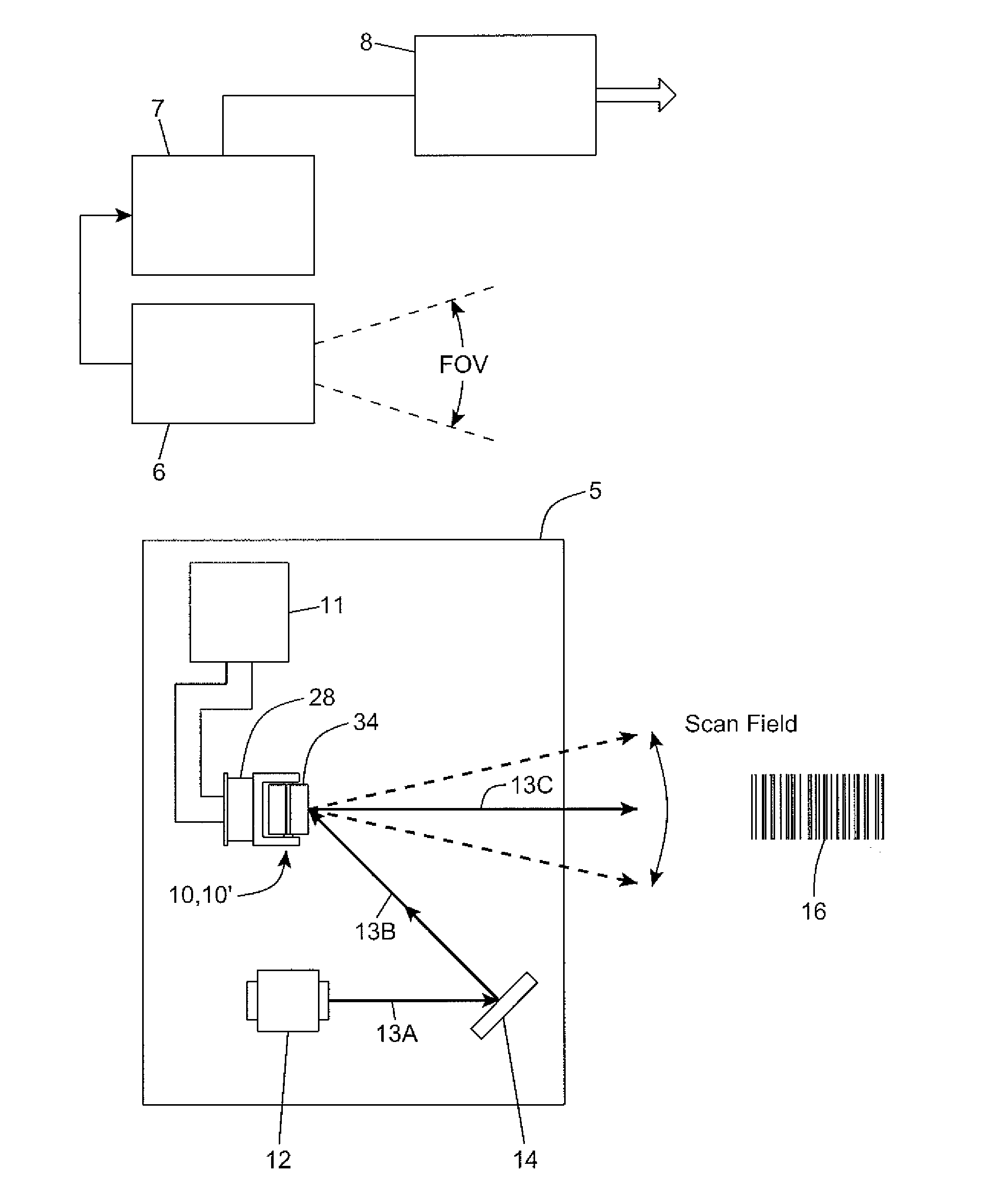
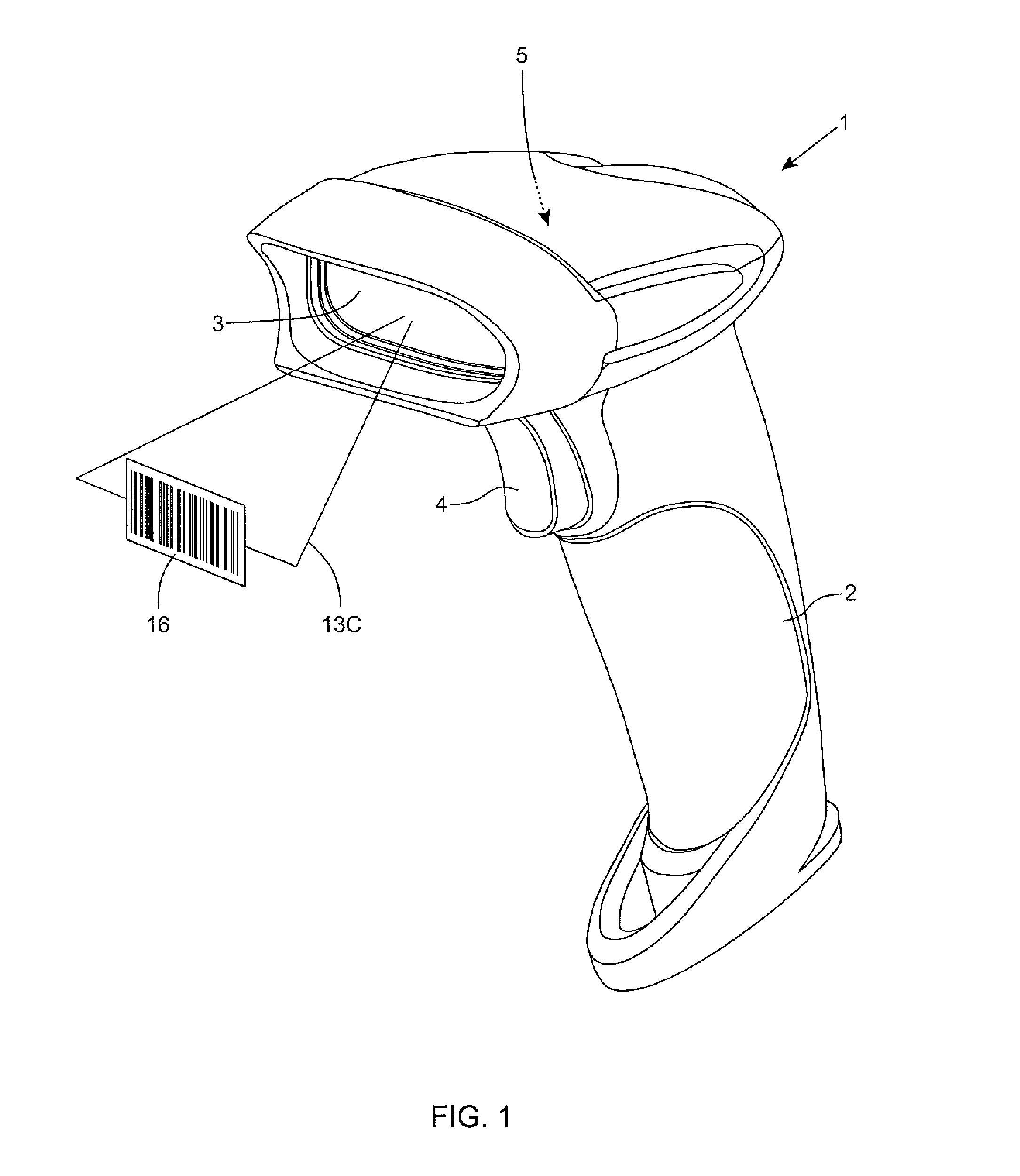
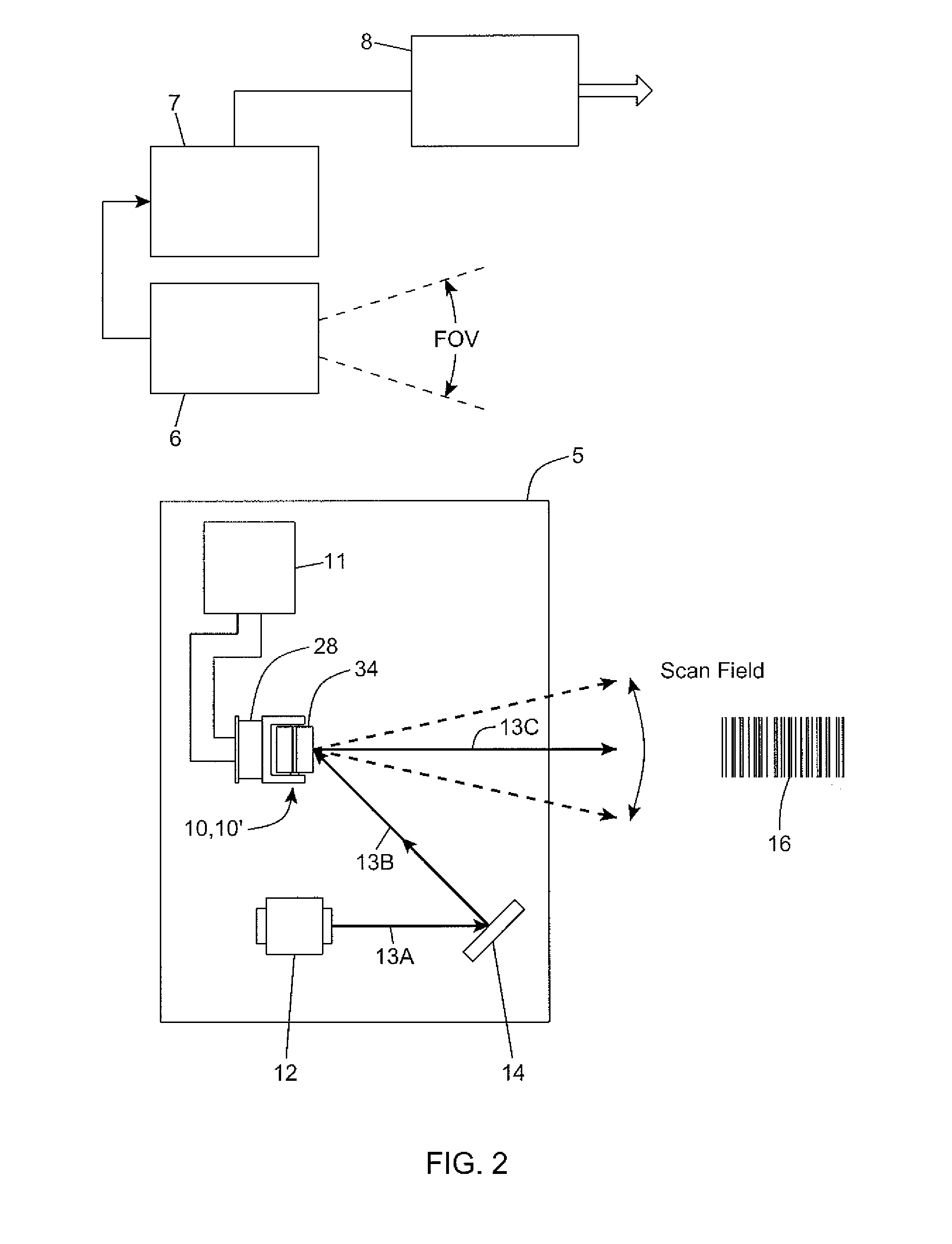
[0027]In general, the laser scanning assemblies 10 and 10′ illustrated in FIGS. 3, 4 and 5, and FIGS. 6, 7 and 8, respectively, and the laser scanning module employing the same shown in FIG. 2, can be embodied with virtually any type of host system requiring the scanning of a laser beam for reading bar code symbols and / or other purposes. However, for purposes of illustration only, the laser scanning assemblies and laser scanning module depicted in FIG. 2 are shown as being embodied within the hand-supportable laser scanning bar code symbol reader 1 illustrated in FIG. 1.

[0028]As shown in FIGS. 1 and 2, the bar code symbol reader 1 comprises: a hand-supportable housing 2; a light transmission window 3 integrated with the housing 2; a manuall...


PUM


Abstract

A laser scanning assembly for use in a host system, including a mirror support element and a permanent magnetic element supported on a flexural element made from flexible material being supported by a pair of shaft half sections forming a stationary shaft, about which an axis of rotation is formed. The mirror support element and the permanent magnetic element have first and second recesses which accommodate the width of the stationary shaft so that a mirror and permanent magnet subassembly, formed by the mirror support element and the magnetic element, is free to oscillate about the stationary shaft when an electromagnetic coil is driven by a drive circuit and generates magnetic forces that act on the permanent magnetic element.

Description

BACKGROUND[0001]1. Field of Invention[0002]The disclosure relates to a new and improved laser scanning assembly for use in laser scanning based bar code symbol readers and other optical instruments.[0003]2. Brief Description of The State of the Art[0004]A critical element in bar code laser scanners is the laser scanning assembly used to scan a laser beam over bar code symbols on objects to be recognized.[0005]For a wide variety of the hand held laser scanners, this element, often called a flipper, involves the oscillating of a mirror which reflects the laser beam when the laser beam leaves the scanner, and in a retro-reflective design, also when the laser beam returns to the scanner after reflecting / scattering off a scanned object in the scan field.[0006]In general, the performance of a laser a barcode scanner is defined by a number of factors including: the accuracy and performance of its scanning element; the dynamic characteristics of the scanning element; the size and mass of th...

Claims


Application Information

Patent Timeline
IPC IPC(8): G06K7/14G02B26/10
CPCG06K7/10633
Inventor GOLANT, VLADIMIR
Owner METROLOGIC INSTR
Why Eureka
Try Eureka