Snubber circuit for buck converter

Inactive Publication Date: 2012-05-10
HONG FU JIN PRECISION IND (SHENZHEN) CO LTD +1
View PDF2 Cites 10 Cited by
  • Summary
  • Abstract
  • Description
  • Claims
  • Application Information

AI Technical Summary

Problems solved by technology

However, while switches such as transistors, and diodes of the buck converters turn on and turn off at a high frequency, a voltage spike can generate and may damage the switches.
To reduce the voltage spike as muc

Method used


Image

  • Snubber circuit for buck converter
  • Snubber circuit for buck converter
  • Snubber circuit for buck converter

Examples


Embodiment Construction

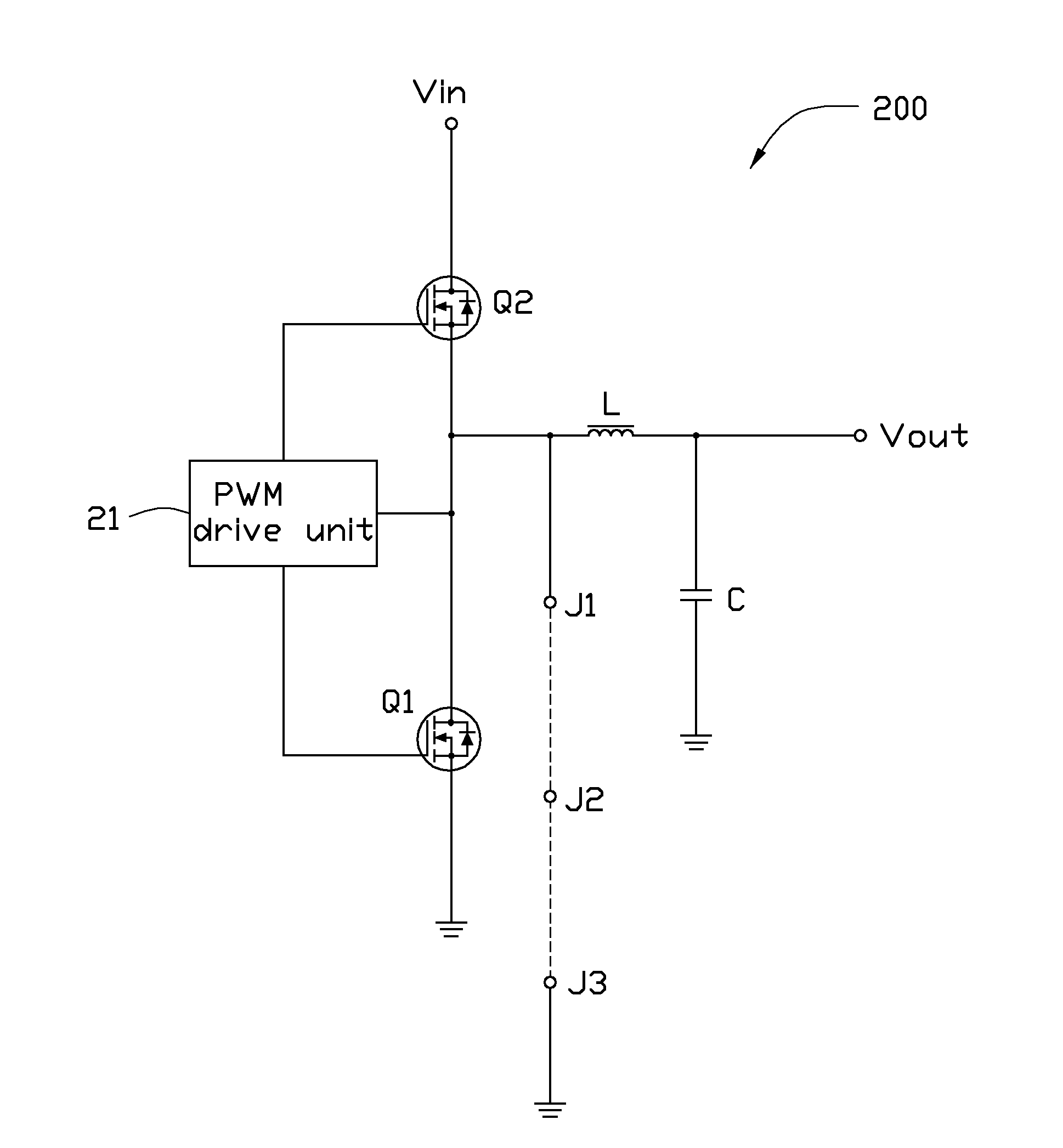
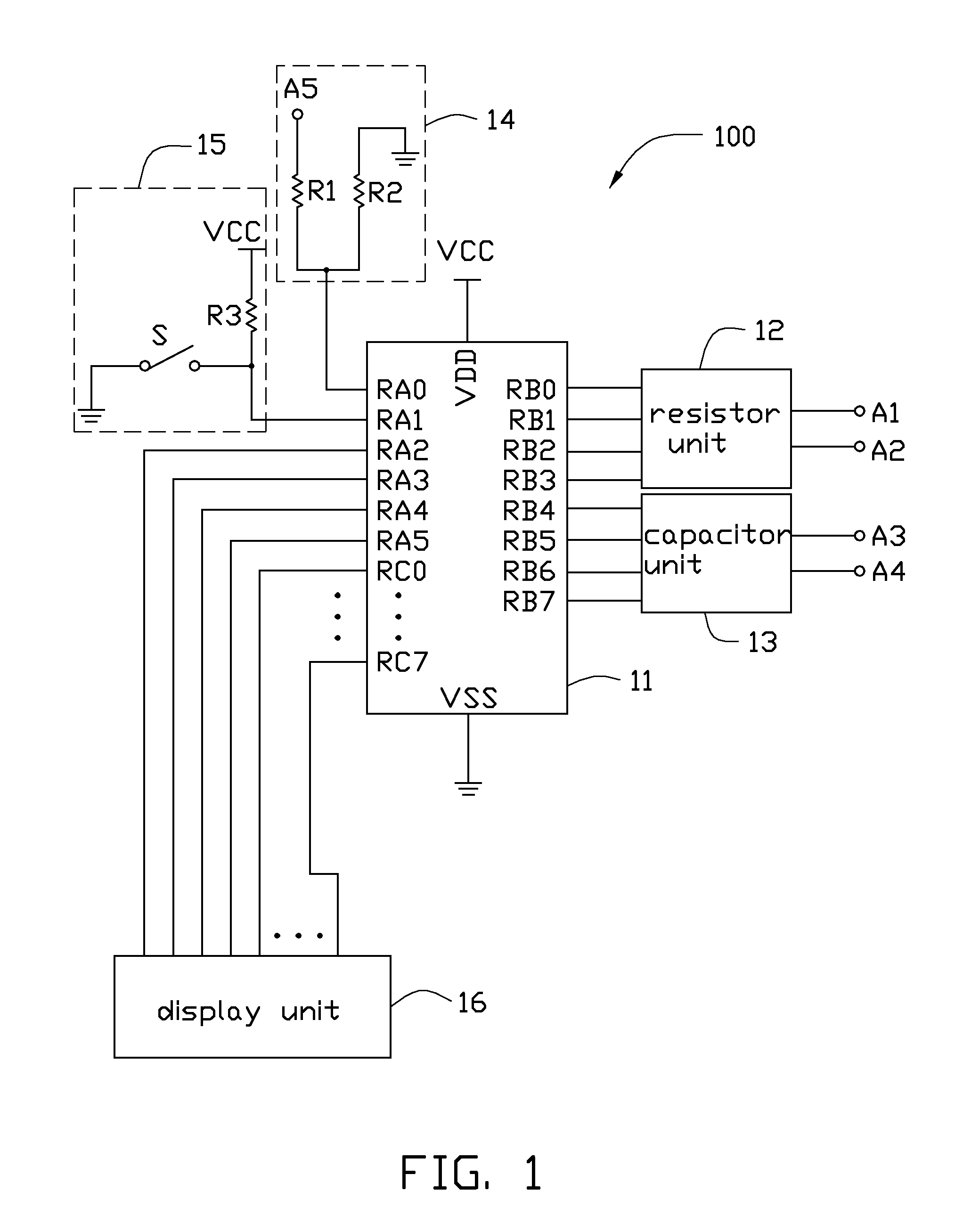
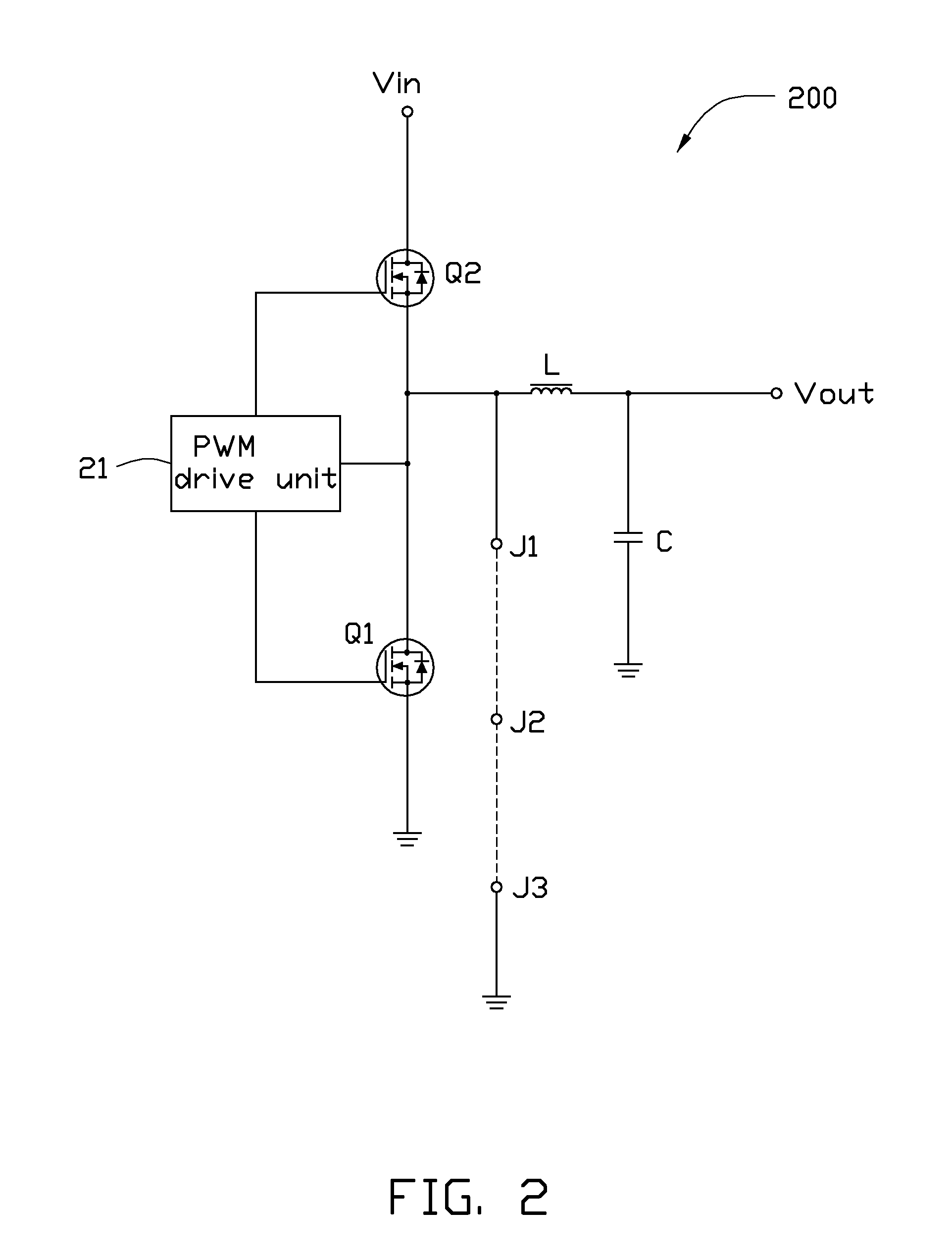
[0010]Referring to FIGS. 1 and 2, a snubber circuit 100 for a buck converter 200, according to an exemplary embodiment, includes a control unit 11, a resistor unit 12, a capacitor unit 13, a detecting circuit 14, a start circuit 15, and a display unit 16. The resistor unit 12, the capacitor unit 13, the detecting circuit 14, the start circuit 15, and the display unit 16 are electronically connected to the control unit 11.

[0011]The control unit 11 includes a power contact VDD, a ground contact VSS, a group of first switch contacts RB0-RB3, a group of second switch contacts RB4 and RB7, a detecting contact RA0, a start contact RA1, a group of display control contacts RA2-RA5, and a group of data transmitting contacts RC0-RC7. The power contact VDD is connected to a power supply VCC. The ground contact VSS is grounded. The group of first switch contacts RB0-RB3 are connected to the resistor unit 12. The group of second switch contacts RB4-RB7 are connected to the capacitor unit 13. The...


PUM


Abstract

A snubber circuit for decreasing a voltage spike of a buck converter includes a resistor unit, a capacitor unit, a detecting unit, and a control unit. The resistor unit provides multiple groups of resistance values. The capacitor unit provides multiple groups of capacitance values. The detecting unit detects voltage spikes of the buck converter corresponding to each group of resistance values and capacitance values. The control unit selects each group of resistance and capacitance to respectively connect to the buck converter and determines a group of resistance and capacitance corresponding to a lowest voltage spike by comparing the detected voltage spikes with each other.

Description

BACKGROUND[0001]1. Technical Field[0002]The disclosure generally relates to snubber circuits for buck converters, and particularly to a snubber circuit for decreasing a voltage spike of a buck converter.[0003]2. Description of Related Art[0004]Buck converters are widely incorporated in power supplies of many electronic devices, due to their fast response, and simple structure. However, while switches such as transistors, and diodes of the buck converters turn on and turn off at a high frequency, a voltage spike can generate and may damage the switches.[0005]A commonly used RC snubber circuit includes a resistor and a capacitor connected in series, and is applied to the buck converter to decrease the voltage spike. To reduce the voltage spike as much as possible, multiple resistors and capacitors need to be used in the buck converter manually to determine a resistance and capacitance suitable for the buck converter, which is inconvenient and time consuming.[0006]Therefore, there is r...

Claims


Application Information

Patent Timeline
IPC IPC(8): G05F1/10H02H9/00
CPCH02M2001/344H02M3/155H02M1/344
Inventor TONG, SONG-LINLUO, QI-YANCHEN, PENG
Owner HONG FU JIN PRECISION IND (SHENZHEN) CO LTD
Why Eureka
Try Eureka