Unlock instant, AI-driven research and patent intelligence for your innovation.

Robot system control method

Active Publication Date: 2012-05-10
PANASONIC CORP
View PDF6 Cites 16 Cited by
  • Summary
  • Abstract
  • Description
  • Claims
  • Application Information

AI Technical Summary

Benefits of technology

[0017]The present invention provides a control method of a robot system that can reduce the time and effort for the operation for establishing “relationship” before “associative movement control”, or select one of a plurality of relationships and reduce the time and effort for the operation for establishing “relationship”. Especially, the present invention provides a control method of a robot system including a welding robot.
[0022]In this method, when there are two industrial robots such as welding robots, by storing the relationship between them and reproducing them at any time point, the time and effort for the operation for establishing the relationship between two industrial robots before “associative movement control” can be reduced. Thus, two arcs are generated by two welding electrodes and welding can be performed at a predetermined position where the two arcs do not interfere with each other, so that the bead shape can be optimized. As a result, welding where the coupling strength is sufficient and the reliability is high can be executed.
[0027]In this method, when there are two industrial robots such as welding robots, by storing a plurality of relationships between them, selecting one of the plurality of relationships, and reproducing them at any time point, the time and effort for the operation for establishing the relationship between two industrial robots before “associative movement control” can be reduced. Thus, two arcs are generated by two torches and welding can be performed at a predetermined position where the two arcs do not interfere with each other, so that the bead shape can be optimized. As a result, welding where the coupling strength is sufficient and the reliability is high can be performed.

Problems solved by technology

This operation is actually extremely troublesome.
However, at the start of the control, it is an issue how “relationship” obtained in welding conditioning work is reproduced and established.
How the relationship can be easily established before “associative movement control” is a common issue for not only the welding robots but also all industrial robots employing “associative movement control”.
However, at the start of the control, it is an issue how one “relationship” is reproduced and established from the plurality of relationships obtained in welding conditioning work.
This issue is also a common issue for not only the welding robots but also all industrial robots employing “associative movement control”.

Method used


Image

  • Robot system control method
  • Robot system control method
  • Robot system control method

Examples


first exemplary embodiment

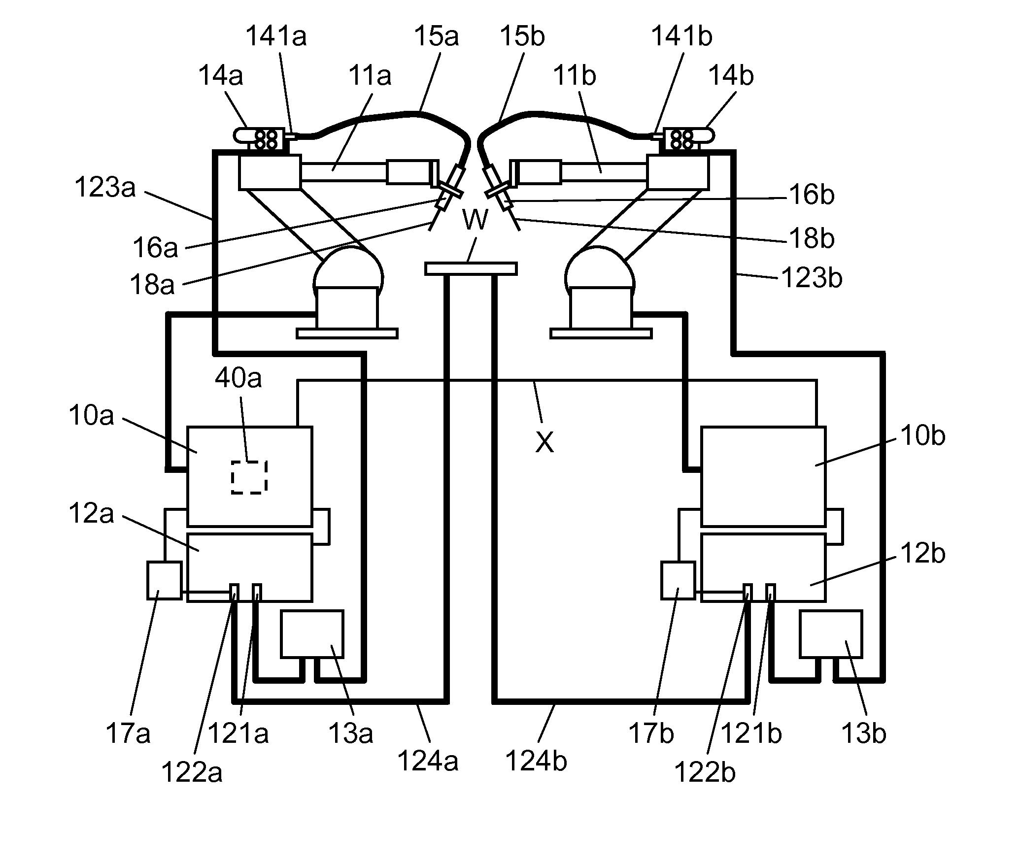
[0041]FIG. 1 is a diagram showing a schematic configuration of a welding system in accordance with a first exemplary embodiment of the present invention. FIG. 1 shows an example where the welding system is formed of two welding robots having a peripheral device or the like. The connecting method between component apparatuses depends on the specification of the component apparatuses, and the configuration of FIG. 1 is one example.

[0042]In a practical welding system, often, the welding robot includes the following elements: a shift moving device that has a manipulator for holding a tool such as a welding torch and moves the position of the manipulator; a positioner that has a base material to be welded and changes the attitude thereof; and a fixture for mounting the base material. However, this welding system is not directly related to the contents of the present embodiment, so that this welding system is not drawn and described.

[0043]In FIG. 1, for purpose of illustration, one of the...

second exemplary embodiment

[0093]FIG. 9 is a diagram showing storing processing in accordance with a second exemplary embodiment of the present invention. FIG. 10 is a diagram showing reproducing processing in accordance with the second exemplary embodiment of the present invention. A control method of a robot system of the present invention is specifically described using FIG. 9 and FIG. 10. The second exemplary embodiment differs from the first exemplary embodiment in the form of the information stored by “storing processing”.

[0094]The information stored by “storing processing” in the first exemplary embodiment is used for reproducing the relationship by “reproducing processing”. This information is simply required to reproduce the relationship, so that the information is not required to be positional data such as Pa and Pb as shown in the first exemplary embodiment, but may be the calculation result of relative position difference Δxyz and relative attitude difference Δuvw as shown in FIG. 8 and expressed ...

third exemplary embodiment

[0097]FIG. 11 is a diagram showing storing processing of a plurality of sets of information in accordance with a third exemplary embodiment of the present invention. FIG. 12 is a diagram showing the reproducing processing of a plurality of sets of information in accordance with the third exemplary embodiment of the present invention. A control method of a robot system of the present invention is specifically described using FIG. 11 and FIG. 12. The third exemplary embodiment differs from the first and second exemplary embodiments in that a plurality of sets of information showing the relationship between both robots is stored by “storing processing” and one set of information is selected from the plurality of sets of stored information and reproduced by “reproducing processing”.

[0098]In the first exemplary embodiment and second exemplary embodiment, one set of information indicating the relationship between both robots is stored, and the reproduction is performed using it. Here, the...


PUM


Abstract

In a control method of a robot system of the present invention, one of two industrial robots is used as a master robot, and the other is used as a slave robot. Data indicating the relation of the relative position and relative attitude between the master robot and the slave robot in welding conditioning work is stored as one set of information. During teaching work, in a state where the master robot and the slave robot exist at any positions, the slave robot is moved with respect to the position of the master robot so as to reproduce the relation of the relative position and relative attitude indicated by the one set of stored information, or the master robot is moved with respect to the position of the slave robot.

Description

TECHNICAL FIELD[0001]The present invention relates to a control method of a robot system when two industrial robots (two sets) that work according to a predetermined program are used and are applied to one object.BACKGROUND ART[0002]Conventionally, in a production site where a welding process is performed, for example, an industrial robot including a welding robot for performing welding work is introduced, and automation and manpower-saving are promoted. Here, “industrial robot” is a generic name for a configuration where a manipulator, a controller, a tool for work, and the other peripheral devices are interconnected. “Welding robot” is a generic name for a configuration where apparatuses and components such as a manipulator, a controller, a welding machine, a welding torch, and a welding electrode, and the other peripheral devices are interconnected. Recently, for improving the efficiency of the welding work, for example, for reducing the time for the welding work, a plurality of ...

Claims


Application Information

Patent Timeline
IPC IPC(8): G05B19/418
CPCB23K9/1062B23K9/1735B25J9/1669Y10S901/02G05B2219/39122G05B2219/39141B25J9/1682
Inventor YOSHIMA, KAZUMASA
Owner PANASONIC CORP