Heat exchanger and method for converting thermal energy of a fluid into electrical power

a heat exchanger and fluid technology, applied in the manufacture/treatment of thermoelectric devices, machines/engines, mechanical apparatus, etc., can solve the problems of high design complexity, achieve the effect of reducing the design complexity of converting thermal energy into electrical power, improving the design of the heat exchanger, and reducing the cost of the process

Inactive Publication Date: 2012-05-17
ROBERT BOSCH GMBH
View PDF2 Cites 23 Cited by
  • Summary
  • Abstract
  • Description
  • Claims
  • Application Information

AI Technical Summary

Benefits of technology

[0018]The cooling channel and / or the flow channel in particular is / are designed to be essentially ring-shaped. Due to the ring-shaped design, it is possible to provide a comparatively large surface area for the volume flow of the flow channel and / or of the cooling channel, this surface area facing the thermoelectric module. The heating power of the hot fluid of the flow channel and / or the cooling power of the cooling medium of the cooling channel may therefore be increased.
[0019]The present invention also relates to an exhaust gas system for an internal combustion engine of a motor vehicle, in which the exhaust gas system has a heat exchanger which may be designed and improved upon as described above. Exhaust gas of the internal combustion engine may flow through the flow channel of the heat exchanger. In particular the flow channel has a catalytic converter in the area of the thermoelectric modules for treating the exhaust gases, so that the exothermic energy of the catalytic converter may additionally be utilized by the thermoelectric modules. The electrical power generated by the thermoelectric modules may be used in particular to supply power to an electronic system of the motor vehicle and / or to charge an automotive battery. Due to the improved design of the heat exchanger to be used, the design complexity for converting thermal energy into electrical power may be reduced.
[0020]The present invention also relates to a method for converting thermal energy of a fluid into electrical power in which at least one thermoelectric module for generating electrical power is connected thermally to the hot fluid only via a flow channel manufactured from a ceramic material for conveying a hot fluid, in particular with the aid of a heat exchanger which may be designed and improved upon as described above. Due to the ceramic flow channel, thermal expansion effects of the flow channel may be reduced, so that the design complexity for converting thermal energy into electrical power may be reduced. The ceramic materials used are preferably manufactured by extrusion. Extruded profiles, which are overdimensioned in length in particular, may be manufactured in this way and then cut to the corresponding required length. This makes it possible to manufacture multiple flow channels and / or cooling channels from a single overdimensioned extruded profile.

Problems solved by technology

One disadvantage of such a heat exchanger is that a high design complexity is required to prevent damage to the thermoelectric module due to thermal expansion effects of the flow channel, for example.

Method used


Image

  • Heat exchanger and method for converting thermal energy of a fluid into electrical power
  • Heat exchanger and method for converting thermal energy of a fluid into electrical power
  • Heat exchanger and method for converting thermal energy of a fluid into electrical power

Examples


Embodiment Construction

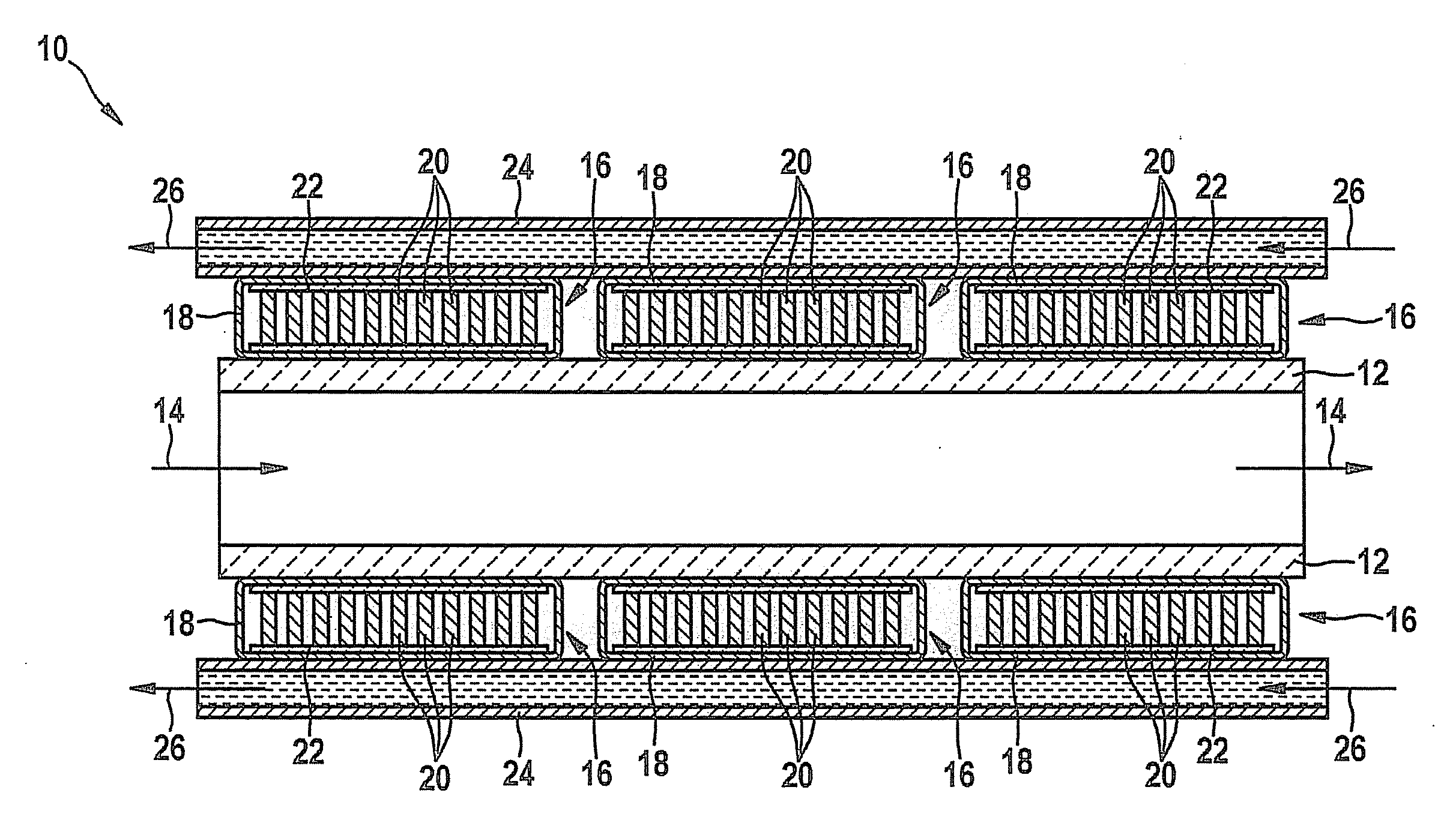
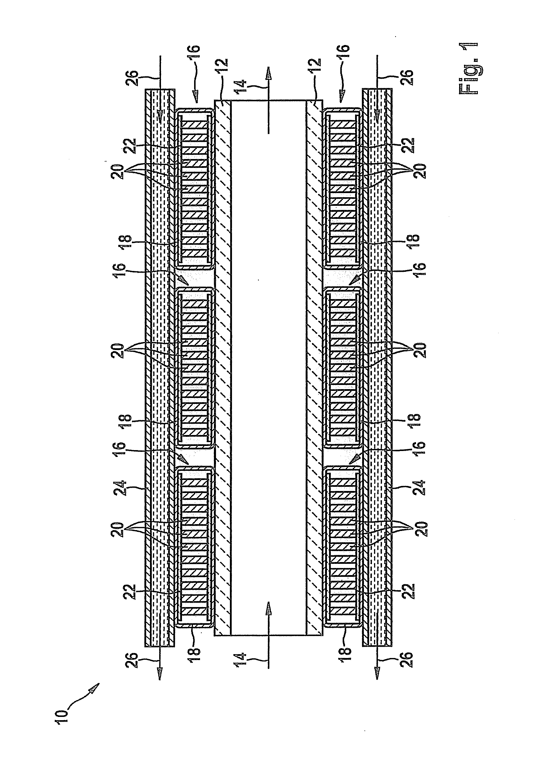
[0024]Heat exchanger 10 shown in FIG. 1 has a ceramic flow channel 12 through which a hot fluid, for example, exhaust gas from an internal combustion engine of a motor vehicle, flows in one direction of flow 14. A thermoelectric module 16 having a metallic sleeve 18 in the exemplary embodiments shown here is connected to ceramic flow channel 12.

[0025]Multiple semiconductor elements 20 clamped between two ceramic disks 22 are situated inside metallic sleeve 18. The side of thermoelectric modules 16 facing away from ceramic flow channel 12 is cooled by an annular cooling channel 24. A cooling medium flows through cooling channel 24 in a cooling direction 26 in countercurrent to direction of flow 14 of flow channel 12.

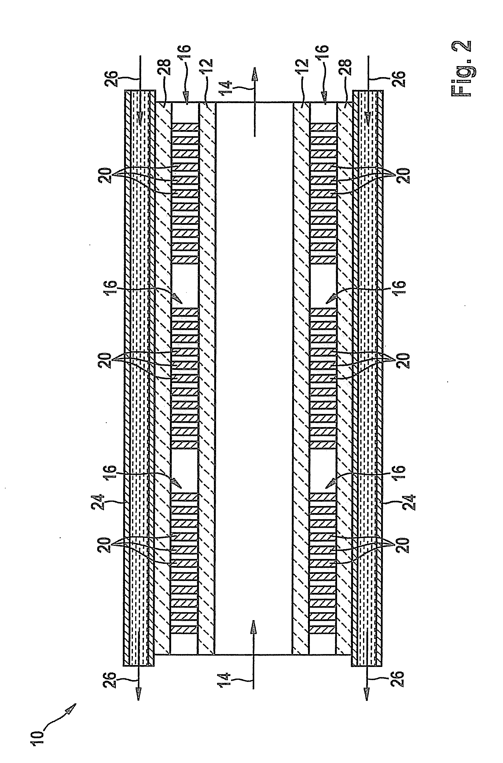
[0026]In heat exchanger 10 shown in FIG. 2, metallic sleeve 18 and ceramic disks 22 have been omitted from thermoelectric module 16 in comparison with FIG. 1, so that semiconductor elements 20 are connected directly to ceramic flow channel 12 by soldering, for example. In...


PUM


Abstract

A heat exchanger for converting thermal energy of a fluid, e.g., exhaust gas of an internal combustion engine, into electrical power, has a flow channel for conveying a hot fluid, and at least one thermoelectric module for generating electrical power is thermally connected to the flow channel. The flow channel is manufactured from a ceramic material. Thermal expansion effects of the flow channel is reduced by the ceramic material of the flow channel so that the design complexity for converting thermal energy into electrical power is reduced.

Description

BACKGROUND OF THE INVENTION[0001]1. Field of the Invention[0002]The present invention relates to a heat exchanger and a method for converting thermal energy of a fluid into electrical power, with the aid of which the thermal energy of the fluid is convertible into electrical power with the aid of a thermoelectric module, in particular in an exhaust gas system of a motor vehicle connected to an internal combustion engine.[0003]2. Description of Related Art[0004]Published U.S. patent application document U.S. 2005 / 0172993 A1 describes a heat exchanger for an exhaust gas system of a motor vehicle. The heat exchanger has a flow channel manufactured from austenitic steel for hot exhaust gas. A thermoelectric module for generating electrical power is thermally connected to the flow channel. With the aid of a metal strip, a passive cooler is pressed against each thermoelectric module, the thermoelectric module being designed to be movable between the flow channel and the passive cooler.[00...

Claims


Application Information

Patent Timeline
Patent Type & Authority Applications(United States)
IPC IPC(8): H01L35/30
CPCF01N5/025Y02T10/16H01L35/30Y02T10/12H10N10/13
Inventor SCHLUCK, PETERMUELLER, BERNHARDBRZOZA, MIROSLAW
Owner ROBERT BOSCH GMBH
Why Eureka
Try Eureka