Radial heat sink with heat pipe set therein

Inactive Publication Date: 2012-05-17
HUANG TSUNG HSIEN
View PDF5 Cites 6 Cited by
  • Summary
  • Abstract
  • Description
  • Claims
  • Application Information

AI Technical Summary

Benefits of technology

[0005]The present invention has been accomplished under the circumstances in view. It is one object of the present invention to provide a radial heat sink that has at least one heat pipe set therein and is practical for use with a CPU, an LED lamp or any other heat-emitting electronic component for quick dissipation of waste heat.

Problems solved by technology

However, simply using the cylindrical base to transfer heat from the attached heat-emitting device to the radiation fins cannot achieve quick dissipation of heat.

Method used


Image

  • Radial heat sink with heat pipe set therein
  • Radial heat sink with heat pipe set therein
  • Radial heat sink with heat pipe set therein

Examples


Embodiment Construction

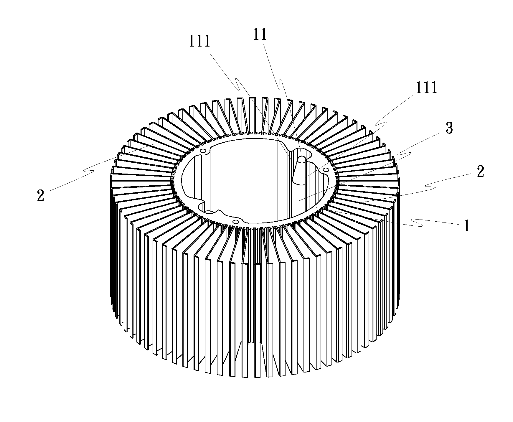
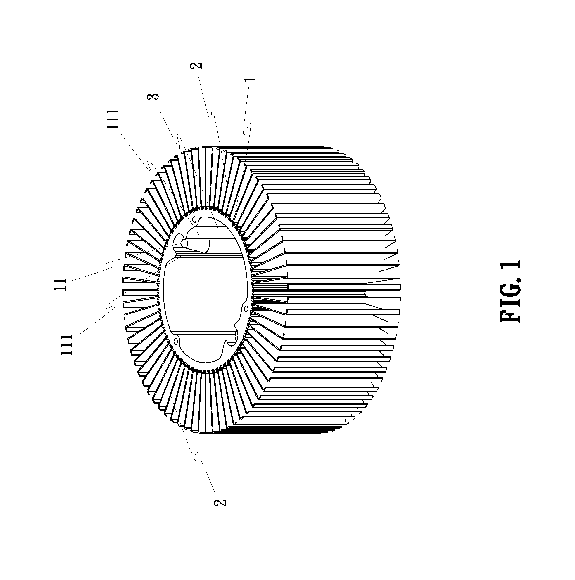
[0033]Referring to FIGS. 1-5, a radial heat sink in accordance with the present invention is shown comprising a core base 1, a plurality of radiation fins 2, and at least one, for example U-shaped, heat pipe 3.

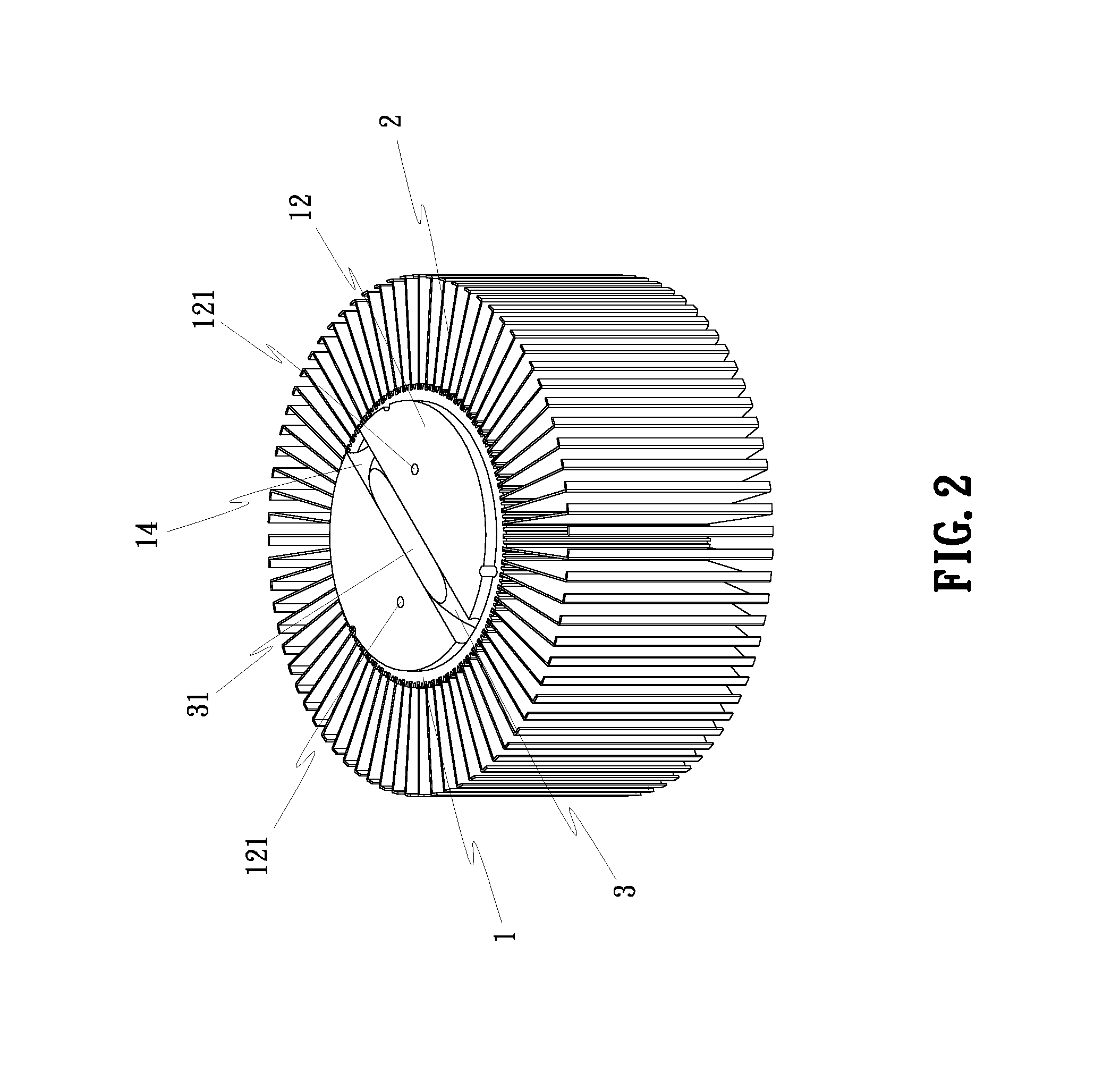
[0034]The core base 1 is a tubular metallic member. The radiation fins 2 are equiangularly fastened to the periphery of the core base 1. The U-shaped heat pipe 3 is mounted inside the core base 1. The core base 1 has mounting grooves 11 located on the inside wall thereof for receiving the U-shaped heat pipe 3. When the two distal ends of the U-shaped heat pipe 3 are respectively press-fitted into one respective mounting groove 11 in the core base 1, the middle part 31 of the U-shaped heat pipe 3 is exposed to the outside of the core base 1 for direct contact with the heat-emitting device (CPU, LED lamp, or any other electronic component part that emits heat during its operation) for quick dissipation of waste heat from the heat-emitting device.

[0035]As shown in FIG. 6, the mou...


PUM


Abstract

A radial heat sink includes a hollow core base with mounting grooves axially located on the inside wall thereof and a locating groove located on an end wall at one end thereof, radiation fins arranged around the periphery of the hollow core base, and heat pipes inserted through the end wall of the hollow core base and press-fitted into the mounting grooves and the locating groove and kept in flush with the end wall of the hollow core base.

Description

BACKGROUND OF THE INVENTION[0001](a) Field of the Invention[0002]The present invention relates to radial heat sink technology and more particularly to a radial heat sink that has at least one heat pipe set therein and is practical for use with a CPU, an LED lamp or any other electronic component that emits heat during its operation.[0003](b) Description of the Prior Art[0004]A conventional radial heat sink is known comprising a cylindrical base and a plurality of radiation fins radially arranged around the periphery of the cylindrical base. The cylindrical base can be a solid or hollow member, and shaped like a round tube, rectangular tube or polygonal tube. This design of radial heat sink is adapted for use with a CPU, an LED lamp or any other electronic component that emits heat during its operation. However, simply using the cylindrical base to transfer heat from the attached heat-emitting device to the radiation fins cannot achieve quick dissipation of heat.SUMMARY OF THE INVENT...

Claims


Application Information

Patent Timeline
IPC IPC(8): F28D15/04
CPCF21V29/006H01L23/427F21V29/773H01L2924/0002H01L2924/00F21V29/717G06F1/20H05K7/20
Inventor HUANG, TSUNG-HSIEN
Owner HUANG TSUNG HSIEN
Why Eureka
Try Eureka