System, apparatus and method for abrasive jet fluid cutting

Inactive Publication Date: 2012-05-17
MCAFEE WESLEY MARK +1
View PDF1 Cites 21 Cited by
  • Summary
  • Abstract
  • Description
  • Claims
  • Application Information

AI Technical Summary

Benefits of technology

[0018]This disclosure relates to the cutting of perforation(s), slot(s), shape(s), and window(s) in submerged down-hole well bore casing(s) whose inside diameter is about 100 mm or larger, and more particularly, to the controlled and precise use of a jet-fluid and nozzle configuration to cut perforation(s), sl

Problems solved by technology

Although simple in concept, the execution of casing window milling is complicated and difficult to achieve in a timely fashion.
Several complicating factors are that the well bore casing is made of steel or similarly hard material and the casing is difficult to access down a deep well borehole.
The sidetrack window entry point machined through the steel casing is narrow at the top, and can cause the sidetracking rotating drill pipe to be damaged and break, because of the rubbing of the rotating drill pipe against the narrow top window opening and burrs left on the machined casing.
Abrasive casing cutting with jet nozzles has been attempted to replace conventional milling, but the present abrasive cutting processes cannot achieve proper casing window cutting required for sidetracking or horizontal drilling.
A deficiency in this prior art method is that the length of the cuts that the disclosed jet nozzle makes into the rock formation is limited because the jet nozzle is stationary with respect to the jet nozzle head.
The offered method is def

Method used


Image

  • System, apparatus and method for abrasive jet fluid cutting
  • System, apparatus and method for abrasive jet fluid cutting
  • System, apparatus and method for abrasive jet fluid cutting

Examples


Example

[0043]Reference will now be made in detail to the present embodiments of the disclosure, examples of which are illustrated in the accompanying drawings. Wherever possible, the same reference numbers will be used throughout the drawings to refer to the same or like parts (elements).

[0044]To help understand the advantages of this disclosure the accompanying drawings will be described with additional specificity and detail.

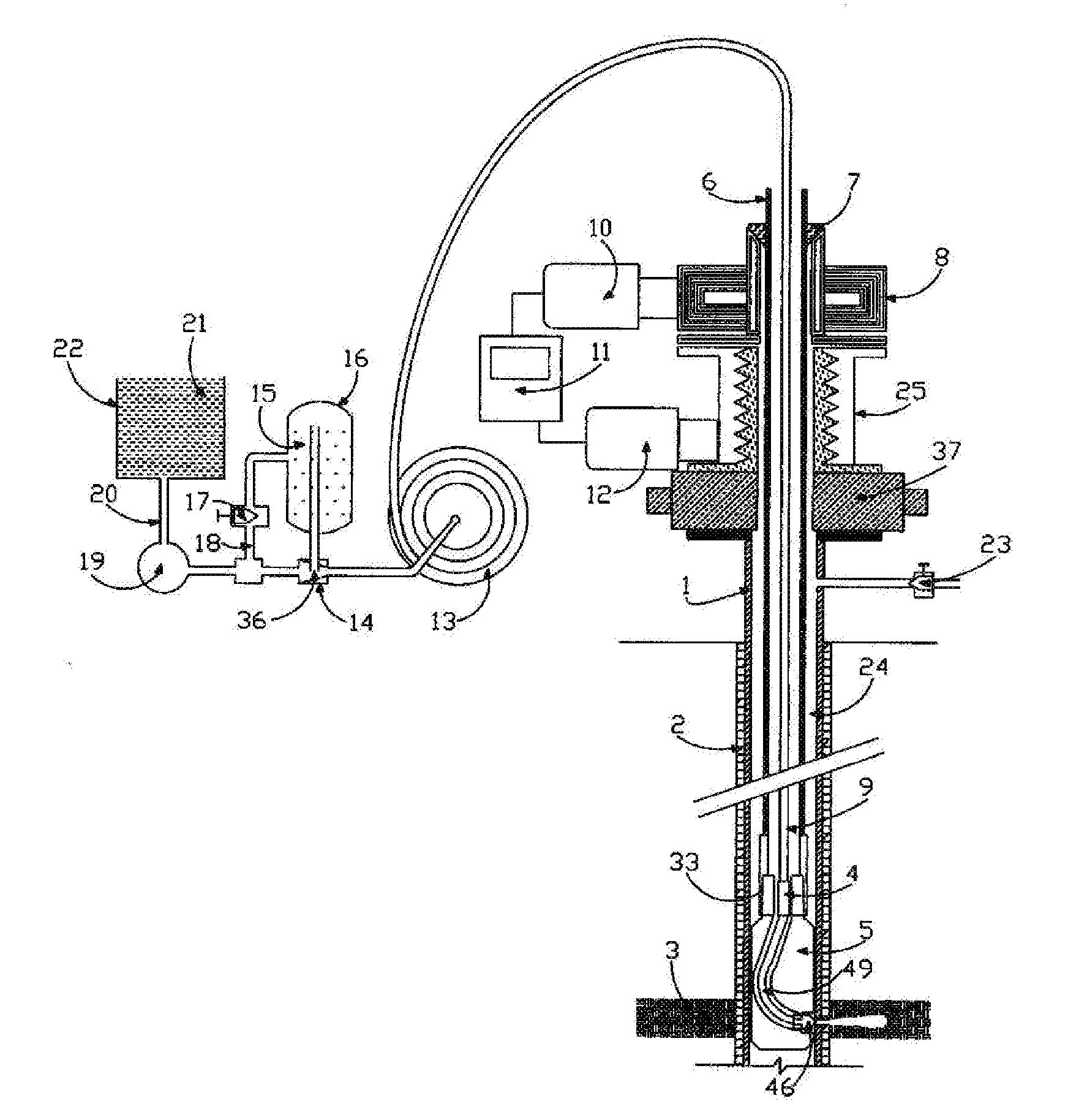
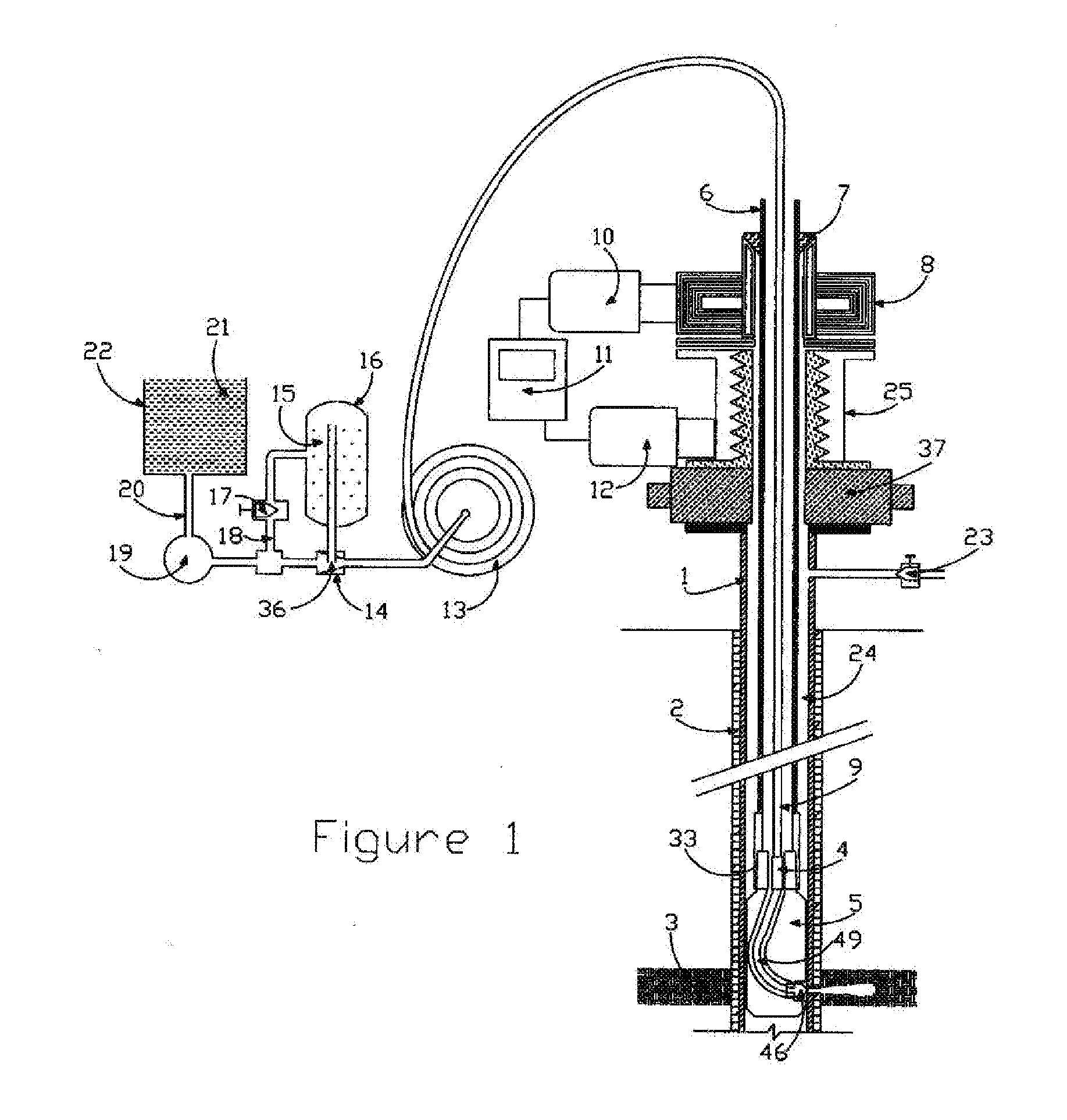
[0045]The present disclosure generally relates to methods and apparatus of abrasive-jet-fluid cutting through well bore casing or similar structure. The method generally is comprised of the steps of positioning a jetting-shoe and jet-nozzle adjacent to a pre-selected location of casing in the annulus, pumping a motive fluid containing abrasives through the jet-nozzle such that the fluid is jetted there from cutting through the casing, while moving the jetting-shoe and jet-nozzle in a predetermined programmed vertical axis and 360 degree horizontal rotary axis.

[0046]I...


PUM


Abstract

A system, apparatus and method for abrasive jet fluid cutting is provided wherein an abrasive jet fluid cutting assembly comprises a hose for receiving a coherent abrasive jet-fluid containing a solid abrasive; a helix/spring attached inside the high-pressure hose; and a jet-nozzle connected to the hose. Wherein the coherent abrasive laden jet-fluid is pumped under high pressure through the high-pressure hose and across the helix. As the jet-fluid traverses the helix, the jet-fluid rotates at a high rate creating a vortex. The disclosed subject matter further includes a system and method for using the abrasive jet fluid cutting nozzle assembly.

Description

[0001]This application is a continuation-in-part of pending U.S. Non-Provisional No. 11 / 938,830, filed Nov. 13, 2007 and entitled “SYSTEM, APPARATUS AND METHOD FOR ABRASIVE JET FLUID CUTTING” which claims the benefit of U.S. Provisional No. 60 / 865,638 filed on Nov. 13, 2006, entitled “SYSTEM AND APPARATUS FOR A JET-FLUID CUTTING NOZZLE” and is hereby incorporated by reference.FIELD[0002]The present disclosure relates to drilling and cutting systems and their methods of operation and, more particularly, to a system and apparatus for a jet-fluid cutting nozzle.BACKGROUND OF THE DISCLOSURE[0003]Many wells today have a deviated bore horizontally drilled extending away from a generally vertical axis main well bore. The use of horizontal drilling technology has increased production fourfold over that previously achieved from vertical wells. The drilling of such sidetracking is accomplished via multiple steps. After casing and cementing a well bore, historically a multi-stage milling proce...

Claims


Application Information

Patent Timeline
IPC IPC(8): E21B43/114
CPCE21B7/18E21B10/60E21B43/114E21B43/112E21B29/06
Inventor MCAFEE, WESLEY MARKALLEY, MARK FRANKLIN
Owner MCAFEE WESLEY MARK
Why Eureka
Try Eureka