Submerged energy storage

a technology of energy storage and submerged water, which is applied in the direction of electric generator control, machine/engine, greenhouse gas reduction, etc., can solve the problems of limited wind power potential without storage options, and achieve the effect of reducing gearing needs, less power, and constant speed of the bubble pump

Inactive Publication Date: 2012-05-17
VAN BREEMS MARTINUS
View PDF7 Cites 12 Cited by
  • Summary
  • Abstract
  • Description
  • Claims
  • Application Information

AI Technical Summary

Benefits of technology

[0020]These are massive but relatively simple objects, whose cost is less than the multi-stage compressors, intercoolers or heat exchangers and heat storage tanks used in conventional CAES plants to compress the air, together with heat recuperators and turbines used in decompression. No fossil fuels are needed. The speed of the bubble pump closely matches the speed of the wind turbine, minimizing the need of gearing.
[0021]The amount of air scooped up in each rotation during the compression phase can be adjusted (to account for varying amounts of power available) by adjusting the height of fluid in the tube. As the fluid level is raised, less air will be captured by the screw, and thus less power will be needed to transport the smaller bubble down. Likewise, in decompression mode, the amount of air introduced into the bottom of the pump can be regulated to produce the needed force to spin the generator at the desired speed.
[0022]Although a single bubble pump per wind turbine is less expensive, there are many advantages to a double pump configuration, i.e. two se

Problems solved by technology

The potential of wind power is

Method used


Image

  • Submerged energy storage
  • Submerged energy storage
  • Submerged energy storage

Examples


Embodiment Construction

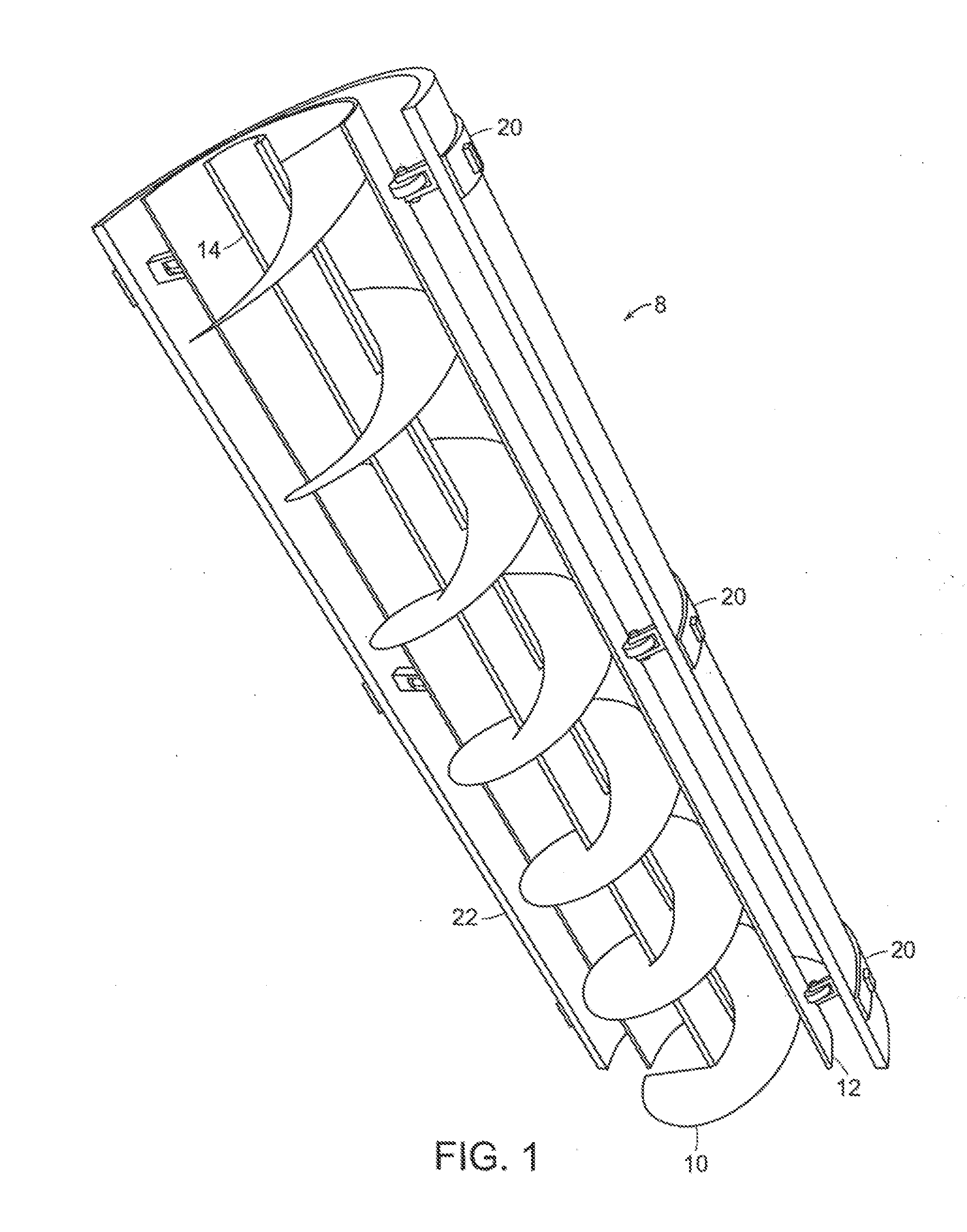
[0031]A pump according to the present invention, as shown in FIG. 1, can be formed of welded steel plate. The pitch and number of blades is dependent on heat transfer rates, but likely there will be between 1-3 blades. Unlike a conventional Archimedes screw, the blades will be welded to the pump shell, so there will be no “leakage”.

[0032]One method to manufacture the pump is to use slotted “washers”, whose ID is about 30-50% of the OD. The washers will have one cut or slit from the ID to the OD. The washers will typically be slid over an aligning pipe, then one edge from one washer will be welded to the edge of the adjoining washer. This process is repeated until the stack is high enough to create a workable length, e.g. 10 m long when pulled apart. The adjoining washers can gradually increase in OD to provide the needed taper for the upper section, although the ID should stay constant for each length.

[0033]When a workable length (for production purposes) of washers has been welded ...


PUM


Abstract

A submerged energy storage system and method incorporates a pump having a helix screw coupled with a storage tank on the sea floor and motive means, such as wind driven impellers or wave motion produced by sliding buoys or driving the screw of the pump.

Description

CROSS-REFERENCE TO RELATED PATENT APPLICATION[0001]This application claims priority from prior U.S. provisional patent application Ser. No. 61 / 341,585 filed Apr. 1, 2010, the entire disclosure of which is incorporated herein by reference.BACKGROUND OF THE INVENTION[0002]1. Field of the Invention[0003]The present invention pertains to systems and methods for storing power / energy in offshore situations where the power source / energy is obtained from wind power or wave power.[0004]2. Brief Discussion of the Related Art:[0005]CAES (Compressed Air Energy Storage) systems offer a proven method of energy storage. Such systems are typically used for energy balancing, allowing electricity produced in off peak time periods to be stored by compressing and storing air, and are a viable alternative to pumped water storage systems. Suitable storage locations are typically underground caverns. However, no suitable geologic location exists in many areas and quoted efficiencies are about 50%, whereas...

Claims


Application Information

Patent Timeline
IPC IPC(8): F03D9/02F03B13/24
CPCF03B13/14F03B13/1845F03B13/20Y02E60/17F05B2240/97Y02E10/72Y02E10/38F03D9/001F03D9/28Y02E10/30Y02E10/727Y02E60/16Y02E70/30Y10T137/86051Y02P80/10F03D9/17F03D13/25
Inventor VAN BREEMS, MARTINUS
Owner VAN BREEMS MARTINUS
Why Eureka
Try Eureka