Scanning patches to provide printer calibration data

a technology of printer calibration and scanning patches, applied in the field of printing, can solve the problems of not being able to assist the operator in performing hand scans with a spectroradiometer or other handheld scanner, and the scheme is not optimized for use with handheld scanners, so as to improve printer throughput, reduce the time required to calibrate printers, and improve the effect of flexibility

Inactive Publication Date: 2012-05-17
EASTMAN KODAK CO
View PDF3 Cites 12 Cited by
  • Summary
  • Abstract
  • Description
  • Claims
  • Application Information

AI Technical Summary

Benefits of technology

[0023]An advantage of this invention is that it removes the need for the operator to always scan patches in a fixed order. It is therefore more robust in the presence of human error than previous schemes. Various embodiments reduce the time required to calibrate a printer and thereby improve printer throughput. This invention can be applied to a wide range of test targets, advantageously providing greater flexibility to the designer of a target. Various embodiments are applicable to a wide range of printing technologies.

Problems solved by technology

However, flatbed scanners are most often colorimetric instruments, not spectroradiometric instruments.
This scheme is, therefore, not optimized for use with handheld scanners.
This scheme permits determining the orientation of a target placed on a flatbed scanner, but does not assist an operator in performing hand scans with a spectroradiometer or other handheld scanner.

Method used


Image

  • Scanning patches to provide printer calibration data
  • Scanning patches to provide printer calibration data
  • Scanning patches to provide printer calibration data

Examples


first embodiment

[0083]In the first embodiment shown (solid arrows), the determining step (step 330) begins with step 410. In step 410, one or more of the scanned patches whose scanned patch data 499 is above a selected threshold are selected. For example, patches with densities (D) above the threshold (i.e., darker than the threshold), luminances (Y) or lightnesses (L*) above the threshold (i.e., lighter than the threshold), or saturations (C*) above the threshold (i.e., farther from neutral than the threshold) can be selected. The units of measurement of the scanned patch data, and the thresholds, can be selected according to the measurement devices available and the requirements of the system. This step uses patches with values above a threshold since they have higher signal-to-noise ratios than patches with values below the threshold, and are therefore more reliable for determining which sets have been scanned than the lower signal-to-noise patches. In one embodiment, step 410 is followed by ste...

second embodiment

[0092]In the second embodiment shown in FIG. 4 (dashed arrows), the determining step (step 330) begins with step 450. Step 450 selects respective signatures for the first and second patch sets on the target, as discussed below. Step 455 receives scanned patch data 499 and produces a signature of the scanned patch data. Steps 450 and 455 can be performed in either order. Step 460 compares the produced signature for the scanned patch data to the selected signatures for the patch sets to determine which patch sets have been scanned.

[0093]Each patch set has a signature. As used herein, the term “signature” means a collection of data uniquely identifying the patch set. That is, the first and second patch sets have different signatures. In various embodiments, the signature of a set is a list or bitmask of which patches in that set have a density (or color, saturation, lightness, or other quantities, as described above) greater than (or equal to) a selected threshold, or less than (or equ...


PUM


Abstract

A method of providing calibration data for a printer includes printing a calibration target using the printer, the target including first and second patch sets, each patch set including a plurality of test patches. An operator scans one or both sets using an external scanner to provide scanned patch data. A processor automatically determines which set(s) have been scanned. Calibration data are automatically generated for the printer using the scanned patch data.

Description

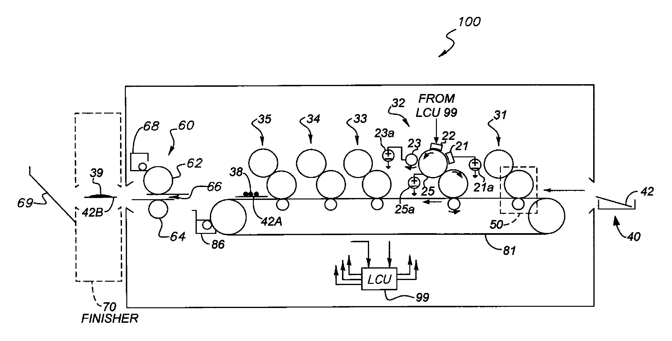
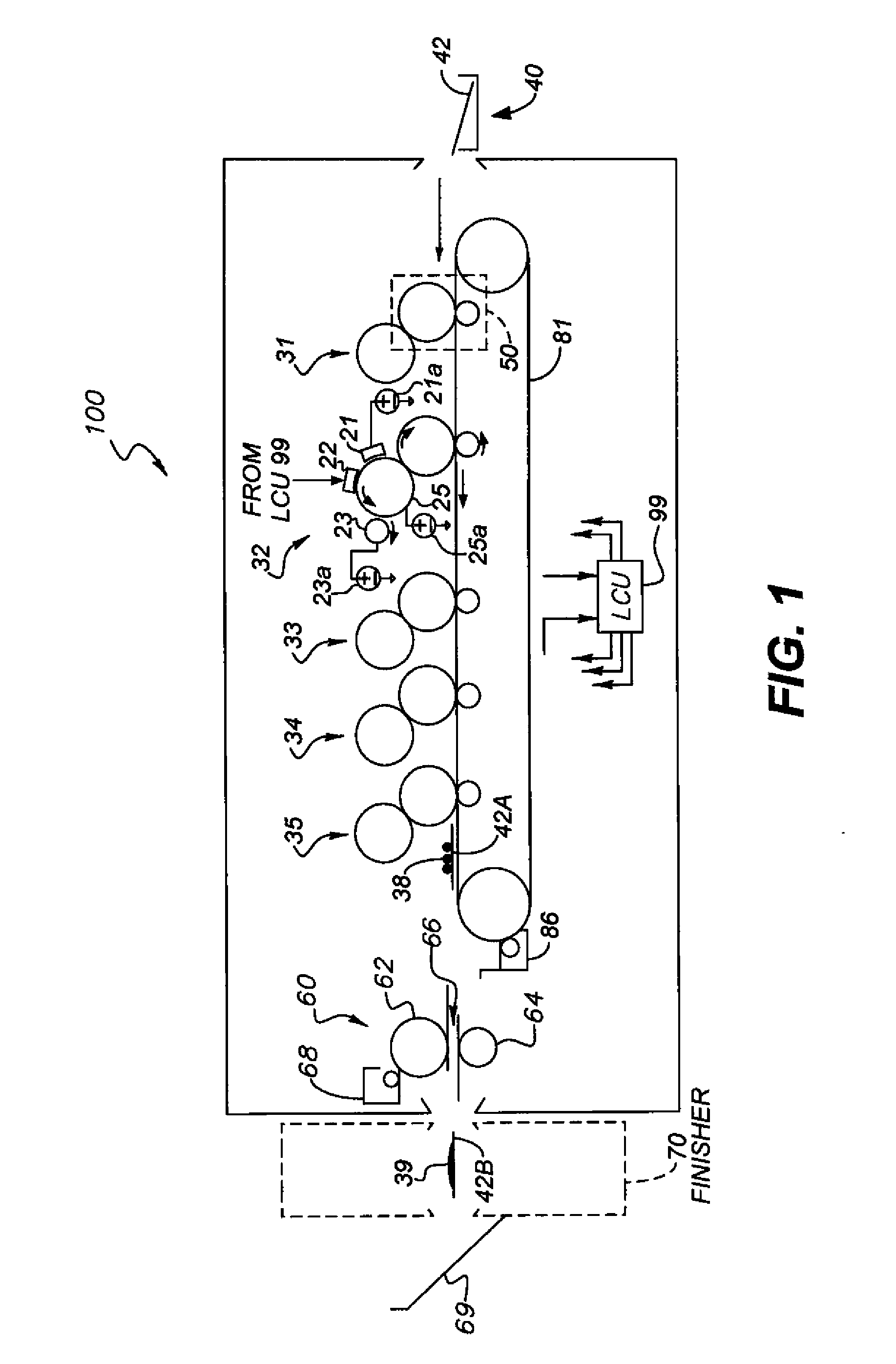
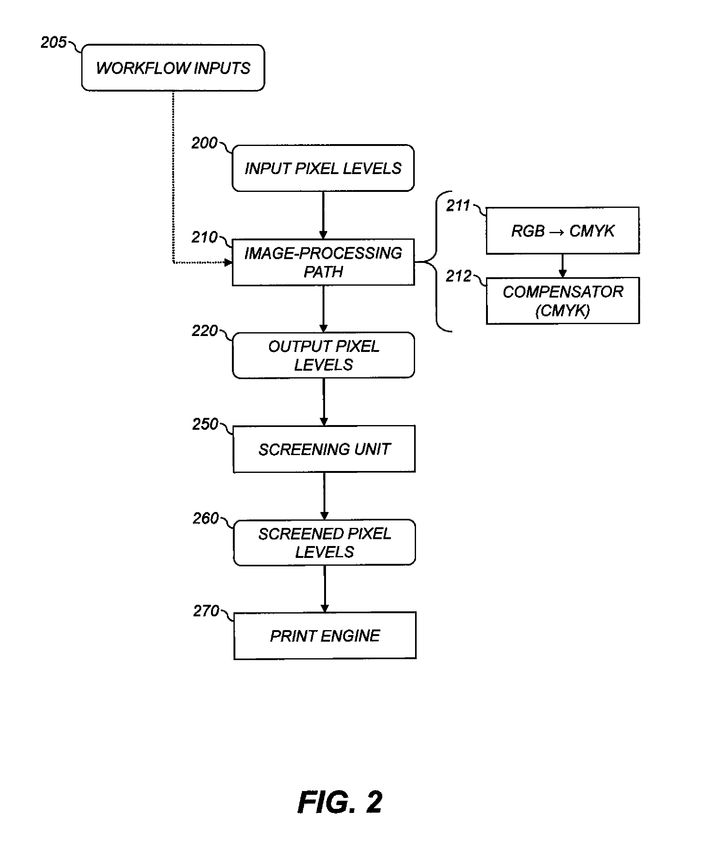
FIELD OF THE INVENTION[0001]This invention pertains to the field of printing and more particularly to color calibration of a printer.BACKGROUND OF THE INVENTION[0002]Electrophotography is a useful process for printing images on a receiver (or “imaging substrate”), such as a piece or sheet of paper or another planar medium, glass, fabric, metal, or other objects as will be described below. In this process, an electrostatic latent image is formed on a photoreceptor by uniformly charging the photoreceptor and then discharging selected areas of the uniform charge to yield an electrostatic charge pattern corresponding to the desired image (a “latent image”).[0003]After the latent image is formed, charged toner particles are brought into the vicinity of the photoreceptor and are attracted to the latent image to develop the latent image into a visible image. Note that the visible image may not be visible to the naked eye depending on the composition of the toner particles (e.g. clear toner...

Claims


Application Information

Patent Timeline
Patent Type & Authority Applications(United States)
IPC IPC(8): G06F3/12
CPCH04N1/6038G06K15/027
Inventor HENDERSON, THOMAS A.
Owner EASTMAN KODAK CO
Why Eureka
Try Eureka