
server

Inactive Publication Date: 2012-05-17
INVENTEC CORP
View PDF12 Cites 0 Cited by
  • Summary
  • Abstract
  • Description
  • Claims
  • Application Information

AI Technical Summary

Benefits of technology

[0009]Accordingly, the present invention is directed to a server, which has a better configuration structure.
[0017]Based on the above, according to the embodiments of the present invention, the electronic modules in the server are vertically inserted in the chassis, and channels perpendicular to the moving direction of the chassis are formed through such configuration of the components, so that the air flow in the chassis is transmitted along the channels, thus improving the heat-dispassion effect in the chassis.
[0018]Moreover, the electronic modules connected to the cable module in the chassis are away from the front panel of the chassis, that is, the electronic modules connected to the cable module are substantially next to the opening of the chassis when the chassis is pulled out from the rack. In this way, the cable module is enabled to extend towards the front panel along the chassis from the electronic modules in the chassis, and thus the cable module is still smoothly disposed on one side of the chassis after the chassis is pulled out by the user, thus avoiding the inconvenience for the user caused by the cables scattered in disorder in the front of the front panel of the chassis.

Problems solved by technology

However, since electronic modules and heat-dissipation devices almost occupy all space in a chassis of the rack server, the heat-dissipation of this kind of server is restricted to a certain extent.
When the electronic modules are disposed at improper positions in the chassis, the extension part of the cables will project in the front of the chassis, resulting in troubles in replacing or repairing the electronic modules in the chassis for the users.

Method used


Image

  • server
  • server
  • server

Examples


Embodiment Construction

[0023]Reference will now be made in detail to the present embodiments of the invention, examples of which are illustrated in the accompanying drawings. Wherever possible, the same reference numbers are used in the drawings and the description to refer to the same or like parts.

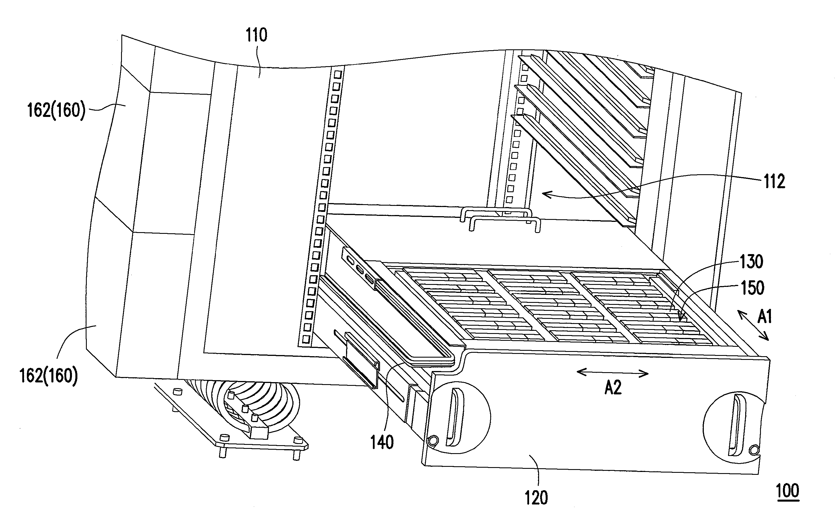
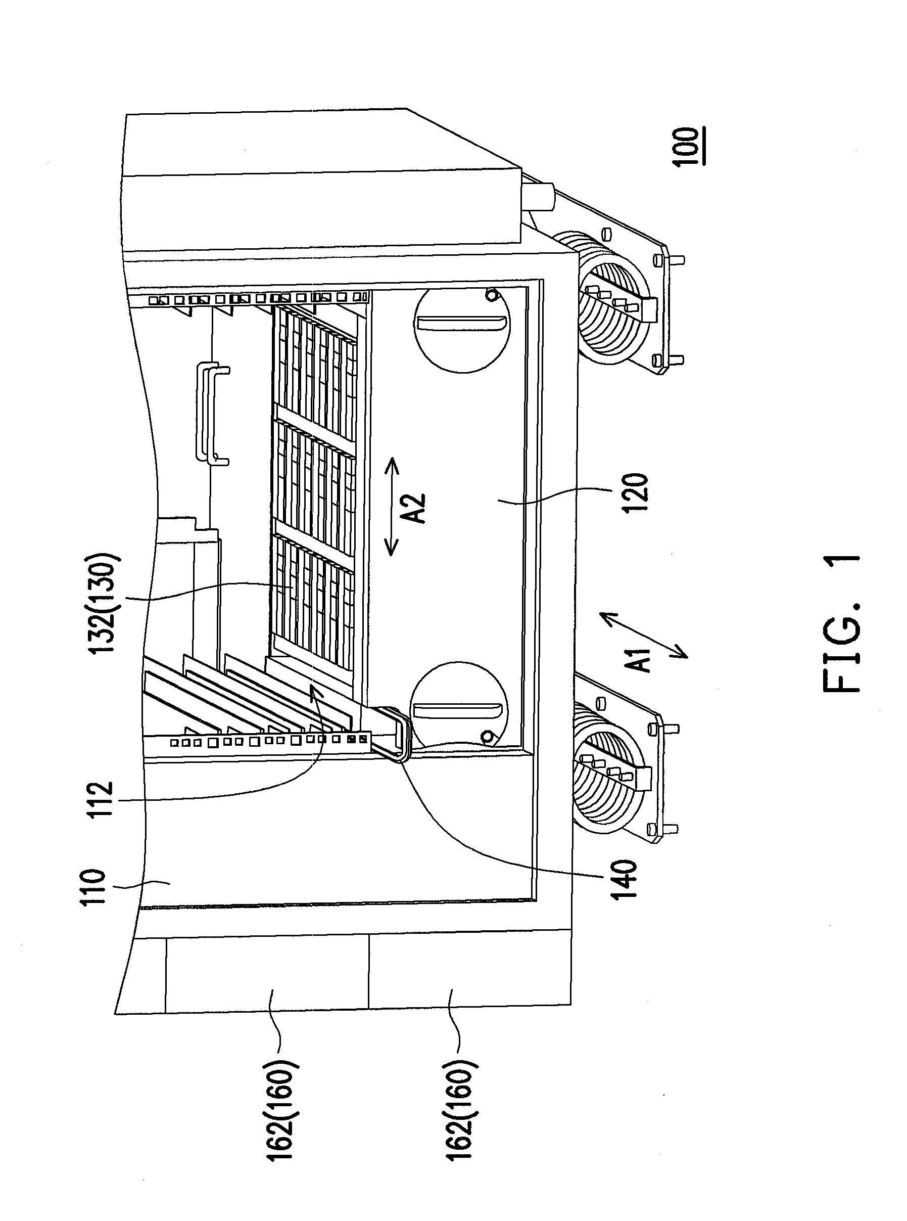
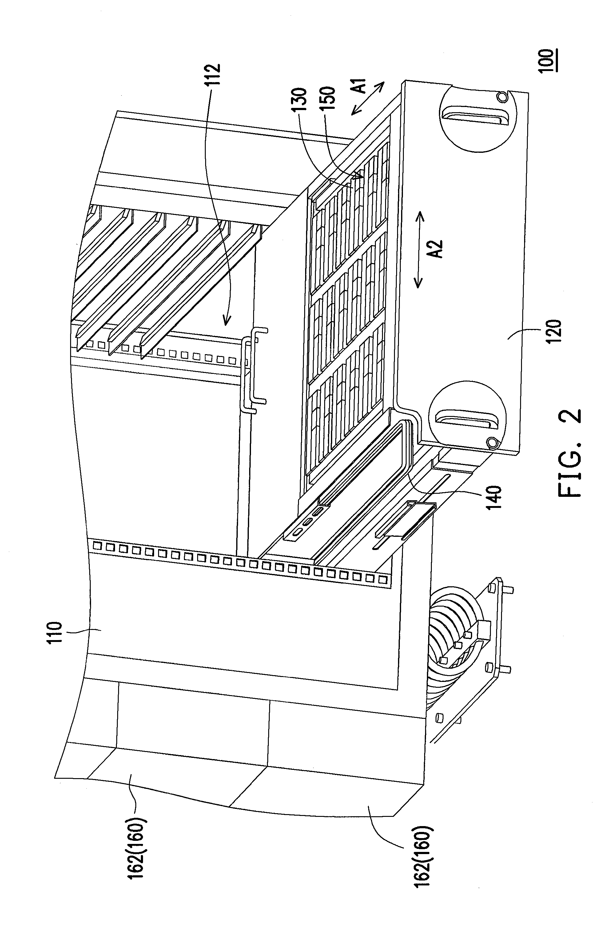
[0024]FIG. 1 and FIG. 2 are schematic views of a server in different states according to an embodiment of the present invention. Referring to FIG. 1 and FIG. 2, in this embodiment, a server 100, for example, is a rack server, and is applicable to an ordinary server product or a cloud computing server product. The server 100 includes a rack 110, at least one chassis 120, a plurality of electronic modules 130 disposed in the chassis 120, and a cable module 140. Here, the case of one chassis 120 is described in the following.

[0025]The rack 110 has an opening 112, the chassis 120 is movably disposed in the rack 110 along a first axis A1, and the chassis 120 is moved in or out the rack 120 through the opening 112. ...


PUM


Abstract

A server including a rack, at least one chassis, a plurality of electronic modules, and a cable module is provided. The rack has an opening. The chassis is movably disposed in the rack along a first axis, and moves in and out the rack through the opening. The electronic modules are vertically and detachably disposed in the chassis. A plurality of channels parallel to a second axis and each of the channels is disposed between two adjacent electronic modules, and the first axis is perpendicular to the second axis. The cable module is disposed at a side of the chassis. The cable module is connected to at least one of the electronic modules. When the chassis is moved out from the rack, the electronic module connected to the cable module is next to the opening of the rack.

Description

CROSS-REFERENCE TO RELATED APPLICATION[0001]This application claims the priority benefit of Taiwan application serial no. 99138883, filed on Nov. 11, 2010. The entirety of the above-mentioned patent application is hereby incorporated by reference herein and made a part of this specification.BACKGROUND OF THE INVENTION[0002]1. Field of the Invention[0003]The present invention generally relates to a server, and in particular, to a server with a configuration structure beneficial to heat-dissipation.[0004]2. Description of Related Art[0005]A server is a core computer providing services for various computers in a network system, which provides functions such as a magnetic disk or printing service for network users, and meanwhile, enables clients to share various resources in the network environment. A basic architecture of the server is approximately the same as an ordinary personal computer, which includes a Central Processing Unit (CPU), a memory, and an Input / Output (I / O) device. The...

Claims


Application Information

Patent Timeline
IPC IPC(8): H05K7/20H05K7/14
CPCH05K7/1491
Inventor CHEN, YI-HSUANYEH, CHI-HUAWU, DE-YANGCHEN, TING-KAILI, CHIN-YUANKUO, CHIH-HAN
Owner INVENTEC CORP
Learn More