
Communication apparatus and communication method, computer program, and communication system

Inactive Publication Date: 2012-05-17
SONY CORP
View PDF6 Cites 68 Cited by
  • Summary
  • Abstract
  • Description
  • Claims
  • Application Information

AI Technical Summary

Benefits of technology

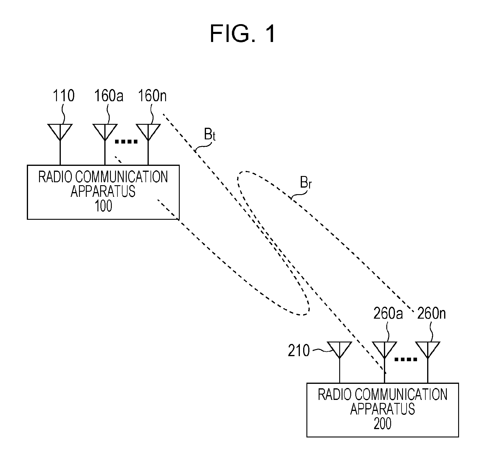
[0038]According to the present invention, it is possible to provide superior communication apparatus and communication method, computer program, and communication system, which can extend the communication distance of millimeter waves by directing the beam of a directional antenna in the direction in which the communicating party is positioned.
[0039]Also, according to the present invention, it is possible to provide superior communication apparatus and communication method, computer program, and communication system, which make it possible to efficiently perform training of an antenna directivity between a transmitter and a receiver, and efficiently feed back the training results from the receiver to the transmitter.
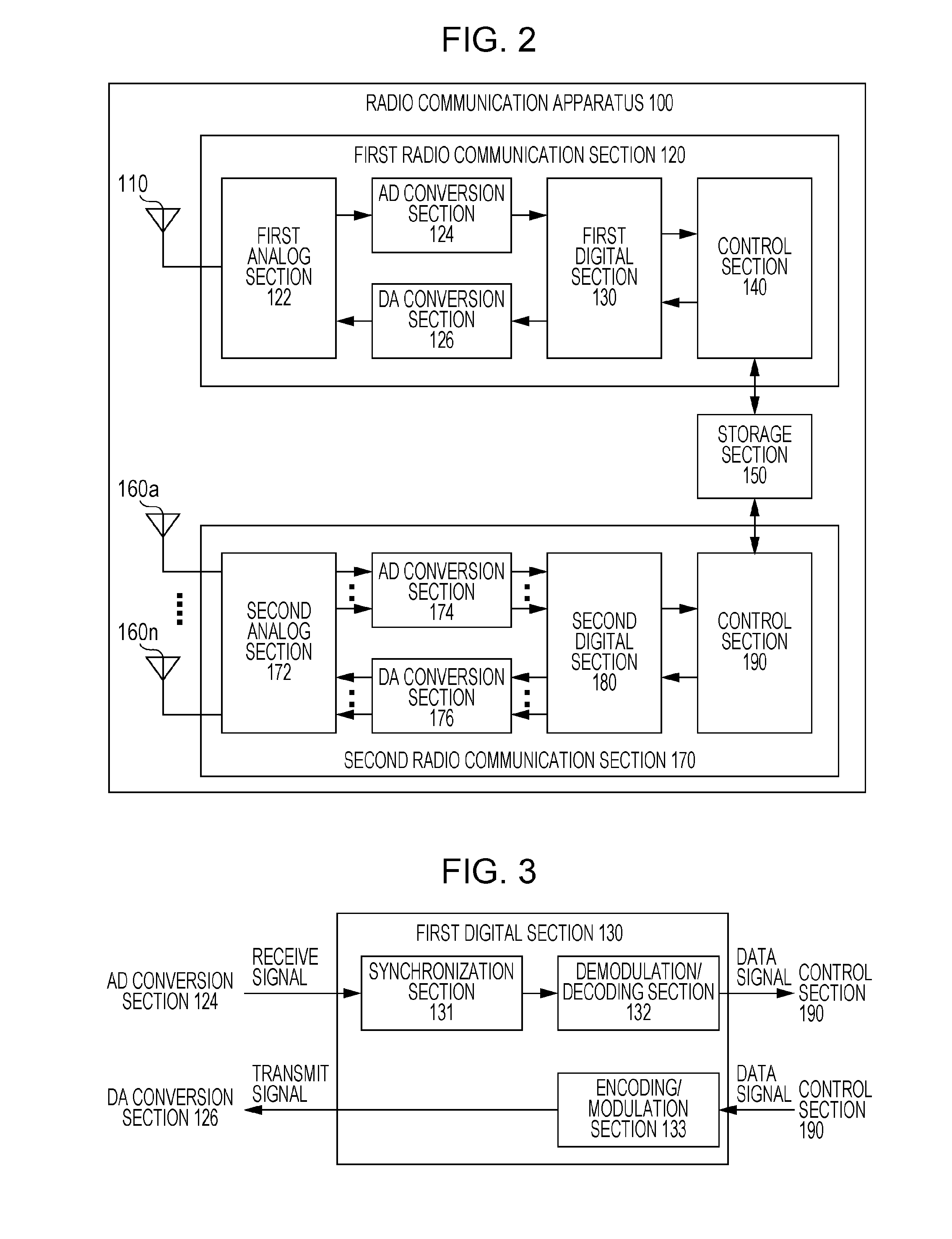
[0040]According to each of the inventions as defined in Claims 1, 8, 9, and 10 of the present application, in a communication system which uses communication according to a first communication mode that is free from the flight distance problem when establishing the directivity of a transmit beam at the transmitting end in a second communication mode using a high frequency band such as millimeter waves, by feeding back information related to an optimal transmit beam pattern to the transmitting end from the receiving end, the directional communication path in the second communication mode is secured to solve the flight distance problem, thereby realizing high speed data communication.
[0041]According to the invention as defined in Claim 2 of the present application, the communication apparatus that operates as the receiving end in the second communication mode can start reception of the beam training signal by the second radio communication section at a reception start timing, which is determined on the basis of reception of an instruction signal instructing training of a beam directivity by the first radio communication section from the transmitting end. Therefore, the header section can be omitted from the beam training signal transmitted in accordance with the second communication mode.
[0042]According to the invention as defined in Claim 3 of the present application, in the case where the method of multiplexing the training signal sequences for each of the transmit beam patterns when transmitting the beam training signal has been shared between the transmission and reception in the second communication mode, the communication apparatus that operates as the receiving end in the second communication mode can estimate an optimal transmit beam pattern corresponding to the training signal sequence that makes the received power maximum or large, and determine feedback information for identifying the optimal transmit beam pattern.
[0043]According to the invention as defined in Claim 4 of the present application, the communication apparatus that operates as the receiving end in the second communication mode feeds back transition of received power over the entire segment in which the beam training signal is received. It is thus possible for the transmitting end to work out not only the transmit beam pattern that realizes the maximum received power but also the beam pattern that provides an effective reflected wave. As a result, when transmitting data frames in the second communication mode, it is possible for the transmitting end to take flexible actions, such as setting not only a single beam pattern that maximizes the received power but also a plurality of beam patterns that provide large received powers as candidates. Also, according to the invention as defined in Claim 5 of the present application, the information volume of feedback information can be compressed by quantizing the received power in a segment in which the beam training signal is received.

Problems solved by technology

On the other hand, since millimeter waves are prone to severe attenuation due to reflection, the radio paths over which to perform communication are mainly direct waves, or reflected waves that are reflected once at most.
Also, millimeter waves have such property that the radio signal does not reach far due to large propagation loss.
In this case, since as many training frames as the number of directional beam patterns need to be exchanged between the transmitter and the receiver, there is a problem in that the time required for training becomes overhead, leading to a decrease in throughput.

Method used


Image

  • Communication apparatus and communication method, computer program, and communication system
  • Communication apparatus and communication method, computer program, and communication system
  • Communication apparatus and communication method, computer program, and communication system

Examples


Embodiment Construction

[0067]Hereinbelow, embodiments of the present invention will be described in detail with reference to the drawings.

[0068]As has been already described in the Background section, radio communication systems utilizing millimeter waves can enlarge their communication range by using a plurality of transmit and receive antennas to form a sharp antenna directivity (i.e., a beam-shaped antenna directivity). However, although the communication distance can be extended by directing the beam in the direction of the position of the communicating party, when in a phase where the beam has not been directed (e.g., when newly entering a network, or when the relative position with respect to the communicating party has changed due to movement of the terminal or the like), frame synchronization cannot be established, that is, even arrival of a frame cannot be detected.

[0069]To perform training of an appropriate beam, one conceivable method is to transmit frames from the transmitting end while varyin...


PUM


Abstract

The directivity of an antenna is efficiently trained between a transmitter and a receiver, and the training results are efficiently fed back from the receiver to the transmitter.In the case where the order of transmit beam patterns corresponding to individual time slots in a beam training signal, and the names representing the respective transmit beam patterns have already been shared through pre-setting or pre-negotiation between the transmission and reception, the receiving end can estimate received power for each time slot on the basis of transition of the received power of the beam training signal, and writes the transmit beam pattern name or time slot number corresponding to the time slot that realizes the maximum received power, in a notification signal for feedback.

Description

TECHNICAL FIELD[0001]The present invention relates to a communication apparatus and a communication method, a computer program, and a communication system which perform radio communication by using millimeter waves, for example, in particular, a communication apparatus and a communication method, a computer program, and a communication system which extend the communication distance of millimeter waves by directing the beam of a directional antenna in the direction in which the communicating party is positioned.BACKGROUND ART[0002]Radio communication called “millimeter wave” can realize higher communication speed by use of high frequency electromagnetic waves. The main uses of millimeter-wave communication include short distance radio access communications, image transmission systems, simplicity radios, and automotive anti-collision radars. Also, at present, technological developments on millimeter-wave communication aimed at promoting its usage are underway, such as realization of l...

Claims


Application Information

Patent Timeline
IPC IPC(8): H04B7/14
CPCH04B7/0617H04B7/063H04B7/0695H04B17/327H04W72/046H04B17/318H04B7/086
Inventor MORIOKA, YUICHITAKANO, HIROAKIKUNIHIRO, TAKUSHI
Owner SONY CORP
Learn More