
Autonomic Hotspot Profiling Using Paired Performance Sampling

a technology of performance profiling and hotspot profiling, applied in the field of optimizing the performance of microprocessors, can solve the problems of less memory requirements for performance profilers, more code analysis, and performance penalties, and achieve the effects of reducing performance impact, reducing code analysis difficulty, and creating performance penalties

Inactive Publication Date: 2012-05-17
IBM CORP
View PDF3 Cites 22 Cited by
  • Summary
  • Abstract
  • Description
  • Claims
  • Application Information

AI Technical Summary

Benefits of technology

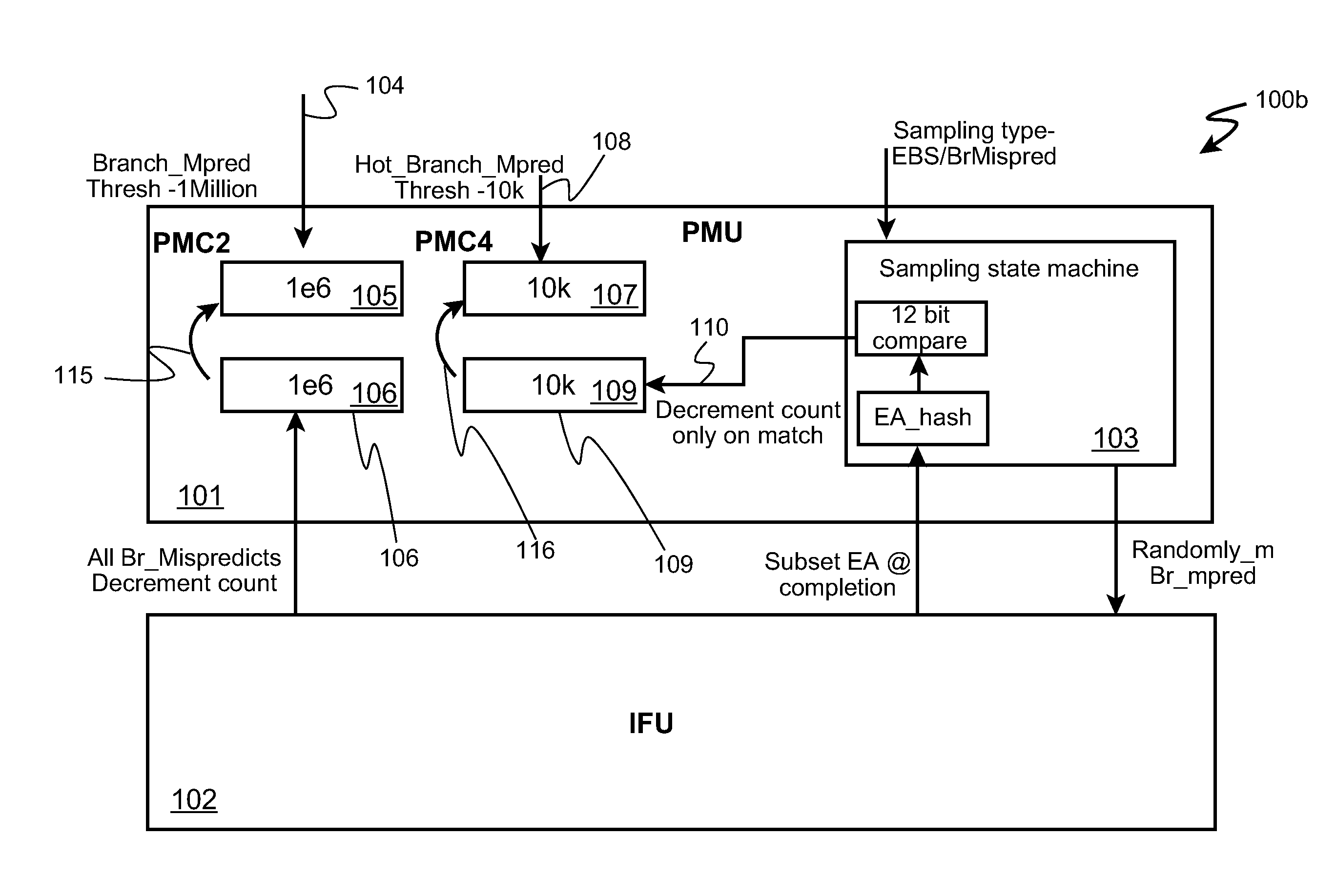
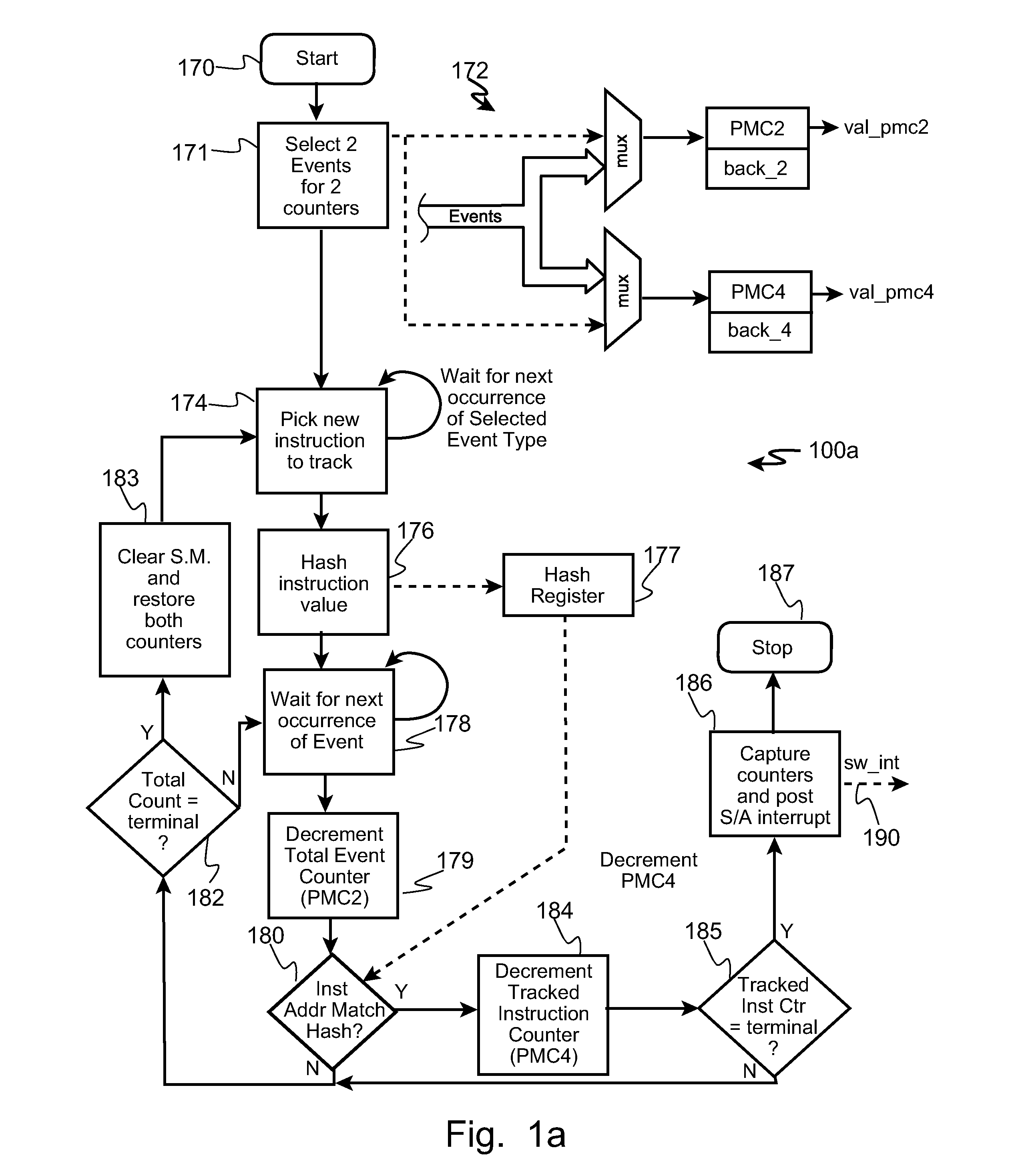
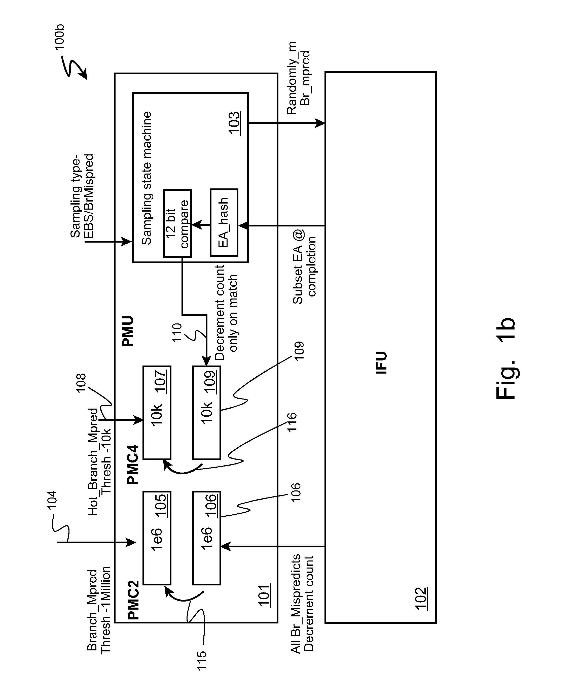
[0012]A processor performance profiler is enabled to for identify specific instructions causing performance issues within a program being executed by a microprocessor through random sampling to find the worst-case offenders of a particular event type such as a cache miss or a branch mis-prediction. Tracking all instructions causing a particular event generates large data logs, creates performance penalties, and makes code analysis more difficult. However, by identifying and tracking the worst offenders within a random sample of events without having to hash all events results in smaller memory requirements for the performance profiler, lower performance impact while profiling, and decreased complexity to analyze the program to identify major performance issues, which, in turn, enables better optimization of the program in shorter developer time.

Problems solved by technology

Tracking all instructions causing a particular event generates large data logs, creates performance penalties, and makes code analysis more difficult.
However, by identifying and tracking the worst offenders within a random sample of events without having to hash all events results in smaller memory requirements for the performance profiler, lower performance impact while profiling, and decreased complexity to analyze the program to identify major performance issues, which, in turn, enables better optimization of the program in shorter developer time.

Method used


Image

  • Autonomic Hotspot Profiling Using Paired Performance Sampling
  • Autonomic Hotspot Profiling Using Paired Performance Sampling
  • Autonomic Hotspot Profiling Using Paired Performance Sampling

Examples


Embodiment Construction

[0018]The inventors of the present invention have recognized a problem not previously addressed or recognized by those ordinarily skill in the art. The inventors discovered that while existing profiling methods are effective in identifying addresses of instructions which cause certain types of events in a processor (e.g. cache hits, branch mis-predictions, etc.), these same current profiling methods do not indicate to analysts or other programs how important or significant each of those instructions at those addresses are in terms of execution frequency. In other words it is possible instruction addresses identified by the existing profiling methods have actually only caused the watched event exactly once, or that it may have caused the event many, many times. So, the inventors have realized that if the profiler's identification of offending instruction instances leads to optimization on an instruction instances which only caused one or relatively few events, the optimization effort...


PUM


Abstract

A processor performance profiler is enabled to for identify specific instructions causing performance issues within a program being executed by a microprocessor through random sampling to find the worst-case offenders of a particular event type such as a cache miss or a branch mis-prediction. Tracking all instructions causing a particular event generates large data logs, creates performance penalties, and makes code analysis more difficult. However, by identifying and tracking the worst offenders within a random sample of events without having to hash all events results in smaller memory requirements for the performance profiler, lower performance impact while profiling, and decreased complexity to analyze the program to identify major performance issues, which, in turn, enables better optimization of the program in shorter developer time.

Description

CROSS-REFERENCE TO RELATED APPLICATIONS (CLAIMING BENEFIT UNDER 35 U.S.C. 120)[0001]None.FEDERALLY SPONSORED RESEARCH AND DEVELOPMENT STATEMENT[0002]This invention was not developed in conjunction with any Federally sponsored contract.MICROFICHE APPENDIX[0003]Not applicable.INCORPORATION BY REFERENCE[0004]None.FIELD OF THE INVENTION[0005]The invention generally relates to technologies for optimizing performance of microprocessors, processing elements and processor cores, especially to the tools and methods for determining sources of performance degradation.BACKGROUND OF INVENTION[0006]Modern microprocessors are very sophisticated compared to those developed two or three decades ago. Some microprocessors are packaged as an individual, discrete device for assembly onto a circuit board, while others are implemented as a “core” or a “processing element” (PE) in a manner which they may be combined with other functions into an integrated circuit (e.g. multiple processors in one package, a...

Claims


Application Information

Patent Timeline
Patent Type & Authority Applications(United States)
IPC IPC(8): G06F9/44
CPCG06F8/4442G06F11/3466G06F11/3471G06F9/3861G06F2201/88G06F2201/885G06F2201/86G06F8/443G06F11/34G06F11/3476
Inventor INDUKURU, VENKAT RAJEEVOWEN, DANIELMERICAS, ALEXANDER ERIKSPANNAUS, JOHN FRED
Owner IBM CORP
Learn More