
Combined intake aspirator venturi tube and water trap in vertical exhaust outlet stack

a technology of exhaust stack and water trap, which is applied in the direction of gas passages, machines/engines, mechanical equipment, etc., can solve the problems of increasing the internal complexity and expense of the exhaust stack as well as the potential for failure, affecting the economic benefits of the system, and affecting the performance of the system

Active Publication Date: 2012-05-24
BLUE LEAF I P INC
View PDF2 Cites 8 Cited by
  • Summary
  • Abstract
  • Description
  • Claims
  • Application Information

AI Technical Summary

Benefits of technology

[0007]Accordingly, the present invention, in any of the embodiments described herein, may provide one or more of the following advantages:
[0011]It is yet another object of the present invention to provide a combined venturi tube and water trap element for use in a generally vertically oriented exhaust stack that may be readily adapted to a wide range of exhaust stack sizes and configurations.
[0013]It is a still further object of the present invention to provide a combined water trap and venturi tube element for use in a generally vertically oriented vehicle exhaust stack that effectively traps and allows removal of a majority of the moisture that may enter the exhaust stack from above the element.
[0014]It is a still further object of the present invention to provide an integral venturi tube and water trap element for use in a generally vertically oriented exhaust stack on a vehicle, the exhaust stack having a catalytic converter element disposed within the portion of the stack and below the element that is durable in construction, inexpensive of manufacture, carefree of maintenance, easily assembled, and simple and effective to use.

Problems solved by technology

If such components are mounted in the vertical exhaust system, there is a possibility that water can enter the upper end of the exhaust system and flow downwardly into contact with the equipment, especially the catalytic converter unit, and potentially damage the components.
The result increases the internal complexity and expense of the exhaust stack as well as the potential for failure.
Such increases are often economically intolerable in the competitive small tractor market sector.

Method used


Image

  • Combined intake aspirator venturi tube and water trap in vertical exhaust outlet stack
  • Combined intake aspirator venturi tube and water trap in vertical exhaust outlet stack
  • Combined intake aspirator venturi tube and water trap in vertical exhaust outlet stack

Examples


Embodiment Construction

)

[0020]Many of the fastening, connection, processes and other means and components utilized in this invention are widely known and used in the field of the invention described, and their exact nature or type is not necessary for an understanding and use of the invention by a person skilled in the art, and they will not therefore be discussed in significant detail. Also, any reference herein to the terms “left” or “right,”“up” or “down,” or “top” or “bottom” are used as a matter of mere convenience, and are determined by standing at the rear of the machine facing in its normal direction of travel. Furthermore, the various components shown or described herein for any specific application of this invention can be varied or altered as anticipated by this invention and the practice of a specific application of any element may already be widely known or used in the art by persons skilled in the art and each will likewise not therefore be discussed in significant detail. When referring to ...


PUM


Abstract

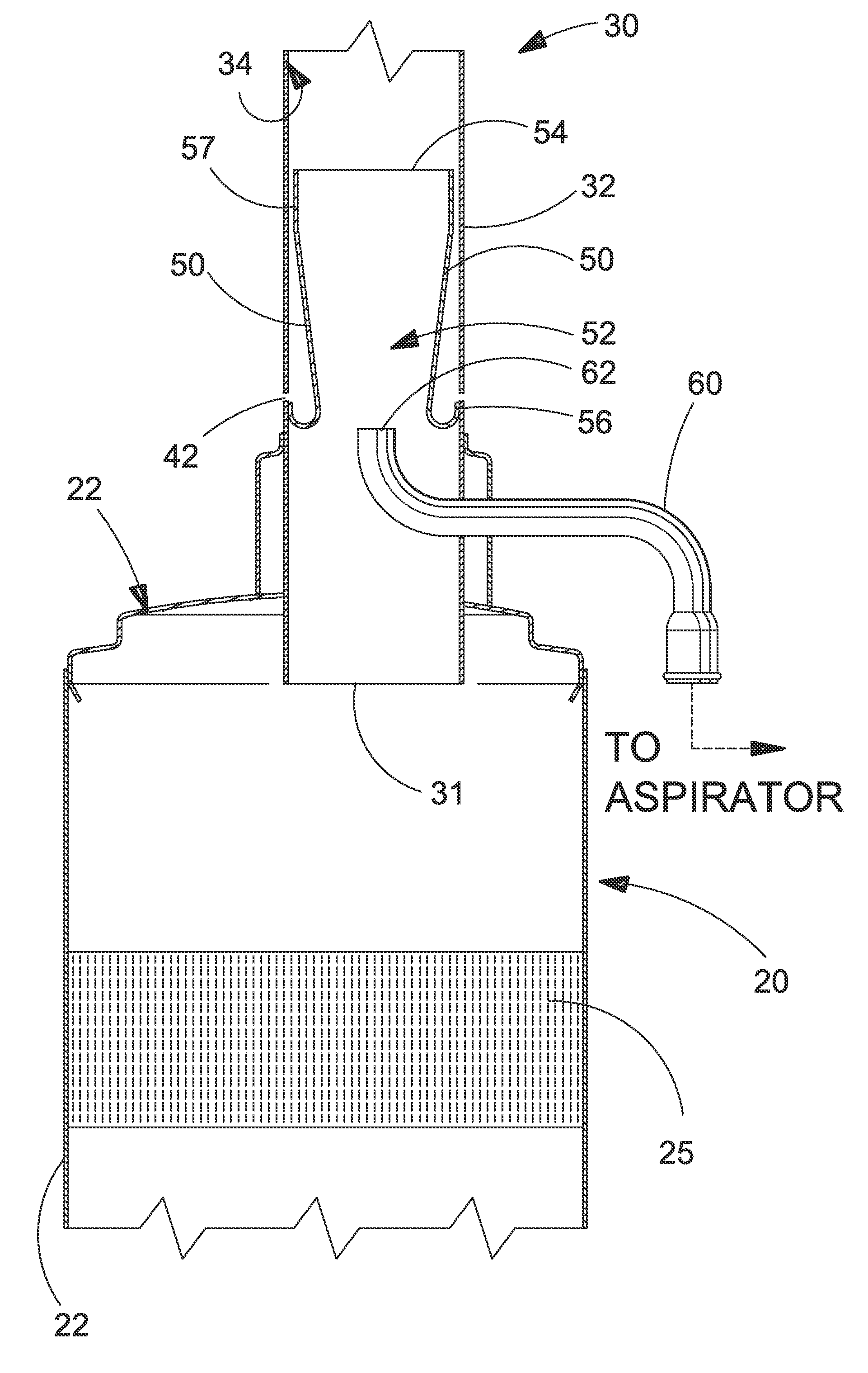
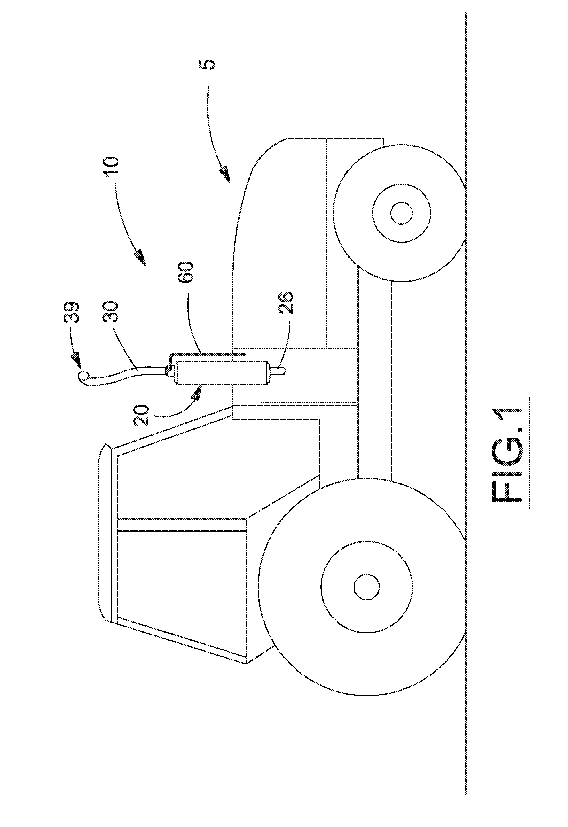
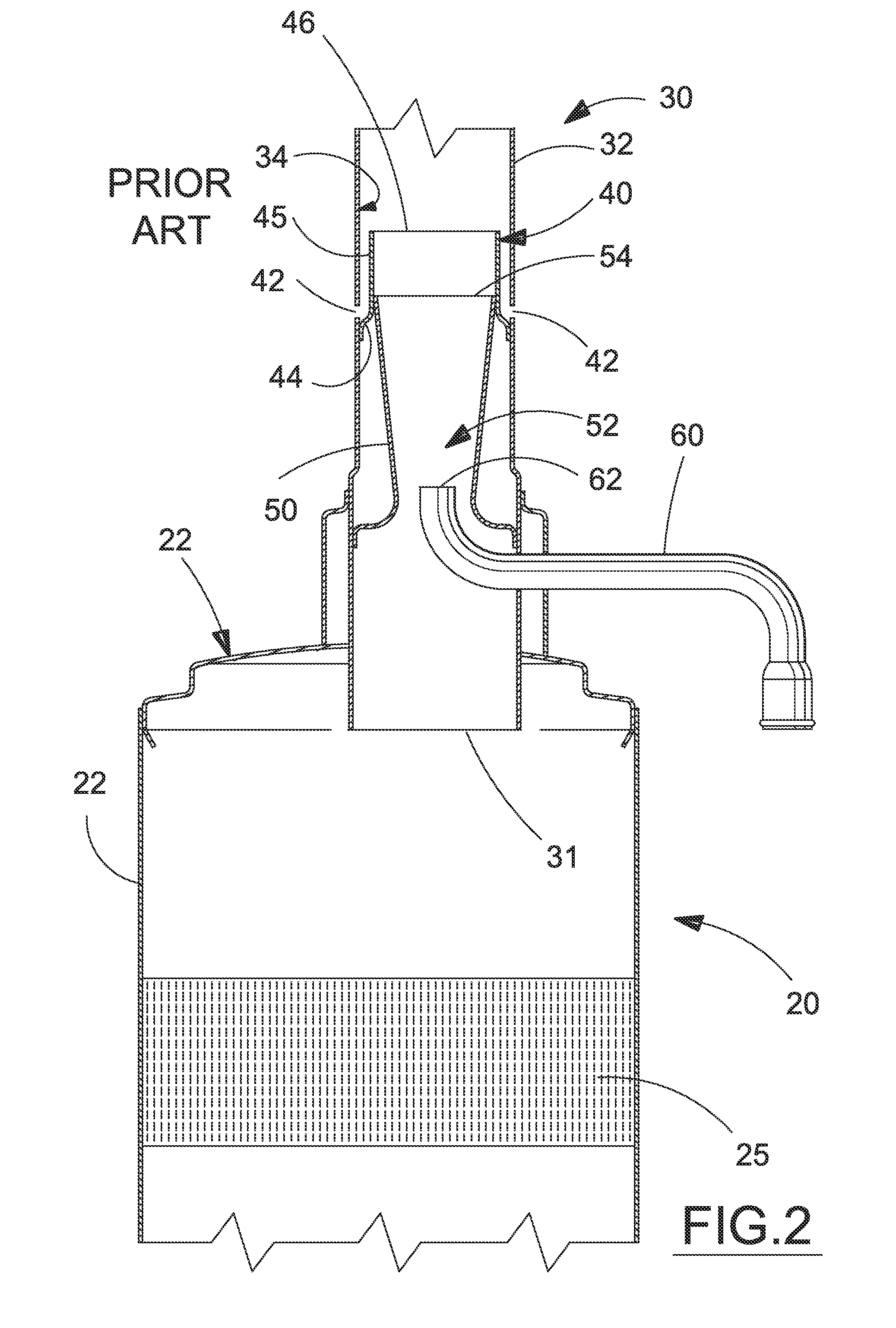
An integral water trap and venturi tube element for use in an exhaust stack on a vehicle, the exhaust stack being generally vertically oriented and having a catalyst element or other moisture-sensitive emission control component disposed below the water trap, the venturi tube having an aspirator tube disposed therein to provide a low pressure aspiration source for the vehicle, wherein the venturi tube is so disposed in the exhaust stack to also function as the water trap and allows capture and diversion of water entering the exhaust stack from above.

Description

[0001]This application claims the benefit of priority of U.S. Provisional Application 61 / 417,125, filed Nov. 24, 2010.BACKGROUND OF THE INVENTION[0002]The present invention relates to an exhaust stack for an off-road work vehicle, and more particularly to combined water trap and aspirator venturi tube structure for a vertical exhaust outlet stack.[0003]Many off-road work vehicles, such as trucks, tractors, off-road equipment, and the like, utilize a vertical exhaust system, in which an exhaust outlet conduit extends vertically from the vehicle. Government regulations designed to reduce engine emissions have required the incorporation of catalytic converters and other moisture-sensitive components in the exhaust system. If such components are mounted in the vertical exhaust system, there is a possibility that water can enter the upper end of the exhaust system and flow downwardly into contact with the equipment, especially the catalytic converter unit, and potentially damage the comp...

Claims


Application Information

Patent Timeline
Patent Type & Authority Applications(United States)
IPC IPC(8): F01N13/00
CPCF01N13/082F01N13/085F01N2590/08F01N2470/30F01N2450/22
Inventor PRENGER, NICHOLAS J.RAJESHWAR, ADUPALAKNOWLES, KAINMOREY, DANIEL A.ADAMSON, WILLIAM H.
Owner BLUE LEAF I P INC
Learn More