Gas filling system and gas filling apparatus

a gas filling system and gas filling technology, applied in the field of gas filling systems, can solve the problems of increasing and reaching the inability to appropriately control the flow rate etc. of the coolant supplied to the cooling means, and the fear of making the driver wait, etc., to achieve suppressing the increase in the temperature of the gas tank, high accuracy, and high accuracy

Inactive Publication Date: 2012-05-24
TOYOTA JIDOSHA KK
View PDF7 Cites 27 Cited by
  • Summary
  • Abstract
  • Description
  • Claims
  • Application Information

AI Technical Summary

Benefits of technology

[0009]According to the invention, the filling flow rate is varied based on the temperature of the gas cooled by the cooling device, so that it is possible to perform optimum filling according to the cooling power of the cooling device. Thus, it is possible to fill a predetermined filling amount of gas (both in the case of the filling amount for a full tank and in the case of the filling amount for a specified filling level) into the gas tank in a minimum period of time while maintaining the inside of the gas tank stable.
[0016]The gas filling system may further include a connection unit for connecting the gas tank and the gas filling apparatus at the time of filling and the gas temperature sensor may detect the temperature of the gas at the connection unit. With this configuration, similarly to the above case, it is possible to minimize the influence of the disturbance on the detected value of the temperature of the gas that has been cooled. In addition, it is possible to increase the applicability, that is, for example, it is possible to utilize the connection unit to install the gas temperature sensor.

Problems solved by technology

However, when a plurality of fuel cell vehicles are consecutively filled up, for example, there is a possibility that the flow rate etc. of the coolant supplied to the cooling means is not appropriately controlled and the temperature of the coolant in the cooling means exceeds a predetermined temperature.
When as a result the hydrogen gas that has not been appropriately cooled is filled into the gas tank, there is a fear that the temperature in the gas tank increases and reaches the design temperature (85° C., for example) before the completion of filling up.
On the other hand, when the filling is stopped because of the insufficient cooling, there is a fear of making the driver wait.

Method used


Image

  • Gas filling system and gas filling apparatus
  • Gas filling system and gas filling apparatus
  • Gas filling system and gas filling apparatus

Examples


Embodiment Construction

[0024]A gas filling system according to an example embodiment of the invention will be described below with reference to the attached drawings. An example of the gas filling system will be herein described, in which hydrogen gas is filled, via a gas filling apparatus, into a gas tank of a fuel cell vehicle equipped with a fuel cell system. As generally known, the fuel cell system includes a fuel cell that generates electricity through electrochemical reaction between fuel gas (hydrogen gas, for example) and oxidant gas (air, for example).

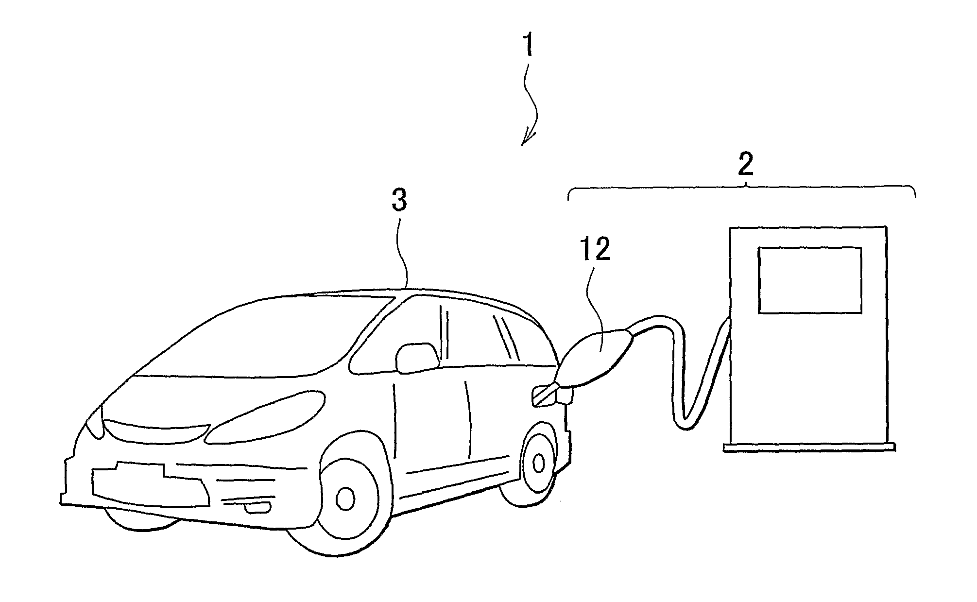
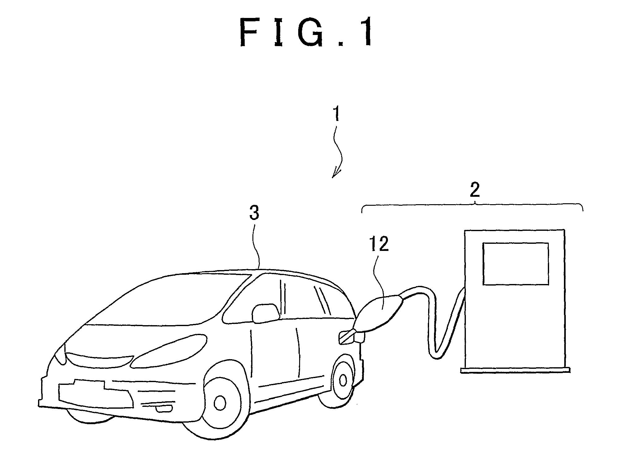
[0025]As shown in FIG. 1, the gas filling system 1 includes the gas filling apparatus 2 that is provided in a hydrogen station, for example, and a vehicle 3 supplied with the hydrogen gas from the gas filling apparatus 2.

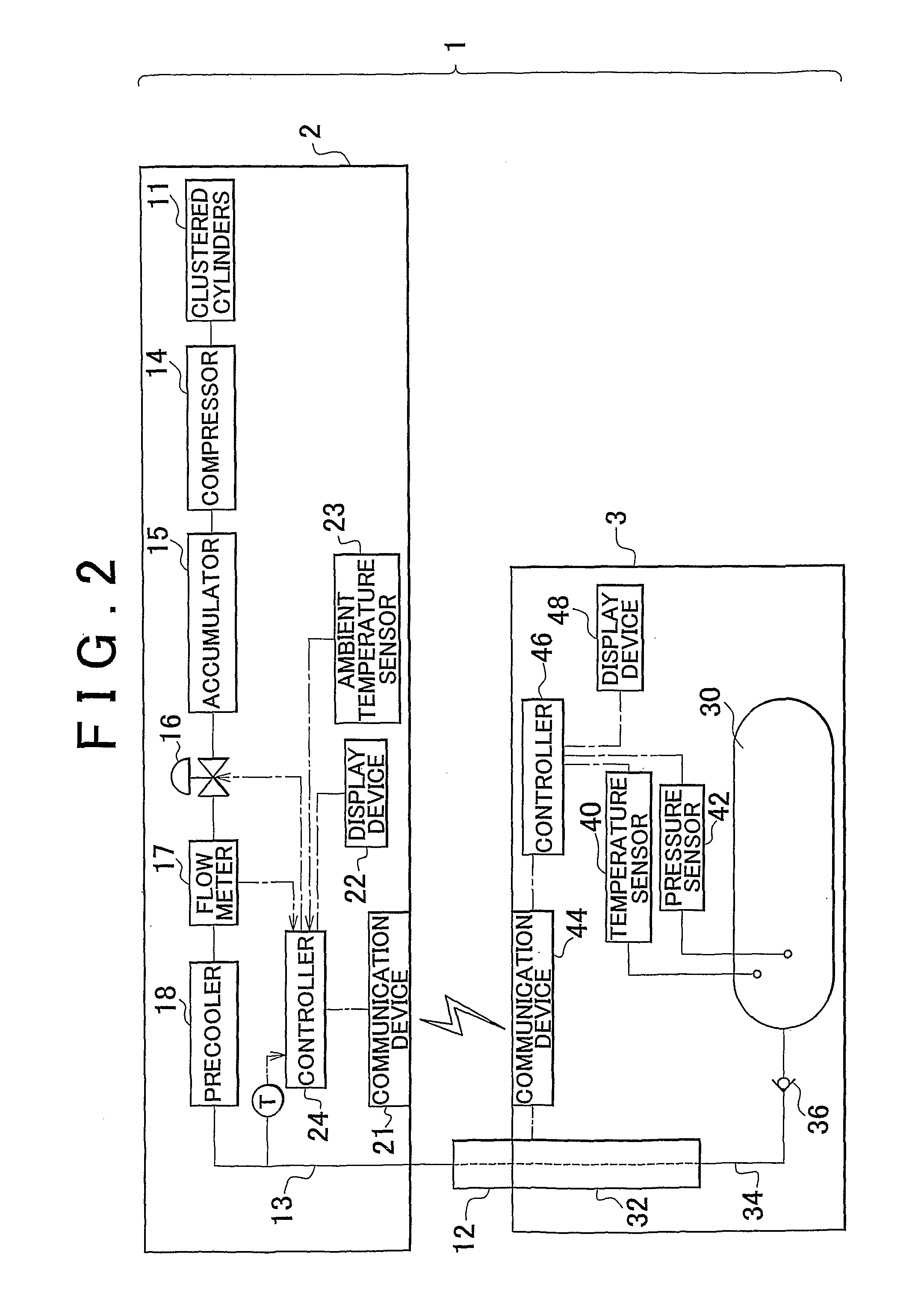
[0026]As shown in FIG. 2, the gas filling apparatus 2 has clustered cylinders (gas supply source) 11 that store hydrogen gas, a filling nozzle 12 that discharges hydrogen gas into an on-board gas tank 30, and a gas line 13 that conn...


PUM

PropertyMeasurementUnit
temperatureaaaaaaaaaa
pressureaaaaaaaaaa

Abstract

A gas filling apparatus in the gas filling system includes a precooler for cooling hydrogen gas supplied from the gas supply source (11) and discharges the hydrogen gas cooled by the precooler to fill the hydrogen gas into the gas tank. The temperature of the hydrogen gas cooled by the precooler is detected by a gas temperature sensor that detects, upstream of the gas tank, a temperature of the hydrogen gas cooled by the precooler. A flow rate controller controls a filling flow rate of the hydrogen gas to be filled into the gas tank, based on the detected temperature of the hydrogen gas. For example, when the detected temperature of the hydrogen gas is high, the filling flow rate is reduced as compared to that when the detected temperature of the hydrogen gas is lower.

Description

BACKGROUND OF THE INVENTION[0001]1. Field of the Invention[0002]The invention relates to a gas filling system for filling gas via a gas filling apparatus installed in a hydrogen station, for example, into a gas tank mounted on a vehicle, for example.[0003]2. Description of the Related Art[0004]At the time of filling fuel gas, a gas-fueled vehicle, on which a gas tank is mounted, such as a fuel cell vehicle, pulls into a gas station and the gas tank is filled with the fuel gas from a filling nozzle of a gas filling apparatus. It is known that when the fuel gas is hydrogen gas, the temperature increases as the fuel gas is filled. A hydrogen gas filling apparatus described in Japanese Patent Application Publication No. 2005-83567 (JP-A-2005-83567) is provided with a cooling means (a so-called precooler) to precool the hydrogen gas by heat exchange with a coolant and the cooled hydrogen gas is filled into the gas tank, so that the time for filling up is reduced. In the hydrogen gas fill...

Claims


Application Information

Patent Timeline
Patent Type & Authority Applications(United States)
IPC IPC(8): B65B57/00
CPCF17C5/06Y02E60/321F17C2205/0134F17C2205/0326F17C2205/0335F17C2205/035F17C2205/0376F17C2221/012F17C2223/0123F17C2223/036F17C2225/0123F17C2225/036F17C2227/0157F17C2227/0341F17C2227/0355F17C2227/0388F17C2250/032F17C2250/043F17C2250/0439F17C2250/0443F17C2250/0495F17C2250/0636F17C2250/075F17C2260/025F17C2265/065F17C2270/0168F17C2270/0184F17C2201/056Y02P90/45Y02E60/32
Inventor INAGI, SHUSUKEMORI, TOMOYUKI
Owner TOYOTA JIDOSHA KK
Why Eureka
Try Eureka