Chip stack device testing method, chip stack device rearranging unit, and chip stack device testing apparatus

a chip stack device and chip stack technology, applied in the direction of measurement devices, semiconductor/solid-state device testing/measurement, instruments, etc., can solve the problems of low finish accuracy at the circumferential part of each chip, difficult to align the respective contact pads with the respective probes of the testing unit, etc., to achieve accurate and efficient testing and low cost

Active Publication Date: 2012-05-24
NIHON MICRONICS
View PDF4 Cites 16 Cited by
  • Summary
  • Abstract
  • Description
  • Claims
  • Application Information

AI Technical Summary

Benefits of technology

[0018]The present invention is accomplished by taking such problems as mentioned above into consideration thereof, and an object thereof is to provide a chip stack device testing method, a chip stack device rearranging unit, and a chip stack device testing apparatus that can test a plurality of chip stack devices having different external sizes accurately and efficiently with low cost.
[0022]With the above configuration, a plurality of chip stack devices having different external sizes can be tested accurately and efficiently with low cost.

Problems solved by technology

However, in a case of a chip stack device configured by stacking a plurality of chips, the respective stacked chips may be displaced from one another, or the finishing accuracy at the circumferential part of each chip may be low.
This makes it difficult to align the respective contact pads with respective probes of the testing unit.
In other words, when the external size of the chip stack device differs with each chip stack device, the positions of the respective contact pads on the upper side surface differ with each chip stack device abutting on the end surface of the tray, which causes a problem in which it is difficult to align the respective contact pads with the respective probes of the testing unit.
(1) The cost for the dedicated unit increases.
Also, in a case of using the dedicated unit, the difference in time in a case where handling time is longer than test time is standby time of the tester, which is wasted time, and the operation efficiency is poor.

Method used


Image

  • Chip stack device testing method, chip stack device rearranging unit, and chip stack device testing apparatus
  • Chip stack device testing method, chip stack device rearranging unit, and chip stack device testing apparatus
  • Chip stack device testing method, chip stack device rearranging unit, and chip stack device testing apparatus

Examples


modification embodiments

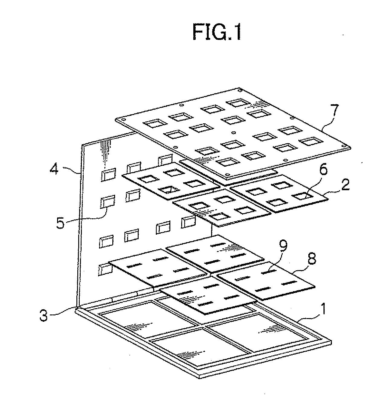
[0083]In the above embodiments, although a plurality of chip stack devices 25 are attached to the sheet tray 21 for chip stack devices, only one device can be attached and tested.

[0084]Also, in the above embodiments, although the chip stack devices 25 are disposed on the sheet tray 21 for chip stack devices with one space inbetween as shown in FIG. 5, they may be disposed with two or more spaces inbetween. In a case where the external dimension of each chip stack device 25 is accurate, the chip stack devices 25 may be disposed with no spaces in a similar manner to the arrangement of the chips 24A of the wafer 24. In this case as well, similar effects to those in the above embodiments can be exerted.

[0085]In the above embodiments, although the testing apparatus has a unit per process with use of the sheet tray cassettes 51 in FIG. 6 for easy understanding of each process, it can be an apparatus that integrates the chip stack device rearranging unit 32, the testing unit 52, and the ca...


PUM


Abstract

A plurality of chip stack devices having different external sizes can be tested accurately and efficiently with low cost. The present invention provides a chip stack device testing method testing a chip stack device configured by stacking a plurality of chips separated by dicing a substrate under test tested in a testing unit. A tray for chip stack devices having equal shape and external dimension to those of the undiced substrate under test is used, one or a plurality of the chip stack devices are attached and supported to an adhesive layer of the tray for chip stack devices to align the chip stack devices with positions of the respective chips of the undiced substrate under test, the tray for chip stack devices is installed in the testing unit in a similar manner to that in a test of the substrate under test, and the respective chip stack devices are tested.

Description

CROSS-REFERENCE TO RELATED APPLICATION[0001]This application claims, under 35 USC 119, priority of Japanese Application No. 2010-261448 filed on Nov. 24, 2010.BACKGROUND OF THE INVENTION[0002]1. Technical Field Relating to the Invention[0003]The present invention relates to a chip stack device testing method testing a chip stack device, a chip stack device rearranging unit, and a chip stack device testing apparatus.[0004]2. Description of Related Art[0005]There is a case in which a plurality of chips on a tested wafer are cut and thereafter tested again.[0006]That is, there is a case in which, after a wafer is cut into chips, these chips are picked up and tested, for the purpose of testing only good chips further strictly. In this case, a tray that supports the plurality of cut chips is required. Examples of such a tray include examples in Patent Document 1 (Japanese Patent Laid-Open No. 2001-91576) and Patent Document 2 (Japanese Patent Laid-Open No. 2000-100882).[0007]First, an in...

Claims


Application Information

Patent Timeline
Patent Type & Authority Applications(United States)
IPC IPC(8): G01R31/26H01L21/66
CPCG01R31/2893G01R31/26H01L22/00
Inventor YASUTA, KATSUOMIYAGI, YUJI
Owner NIHON MICRONICS
Why Eureka
Try Eureka