System and method for microwave ranging to a target in presence of clutter and multi-path effects

a microwave range and clutter technology, applied in the field of electromagnetic distance measurement, can solve the problems of limited bandwidth of transmitted pulses, multipath effects, and difficult isolation of individual targets, and achieve the effect of high clutter

Active Publication Date: 2012-05-24
AMTECH SYST
View PDF4 Cites 19 Cited by
  • Summary
  • Abstract
  • Description
  • Claims
  • Application Information

AI Technical Summary

Benefits of technology

[0023]The present invention achieves the stated objectives as well as others while overcoming difficulties of the prior art. The techniques of the present invention can be applied to other radar systems using the principles described below.
[0024]In an embodiment of the invention, there is a system for measuring the range to an RFID tag including situations containing high clutter and multi-path signals, is disclosed. The system includes an RFID reader; an RFID tag; and a coordinated pulse radar system. In the system, the RFID reader causes the tag to respond to received signals in a first backscatter s

Problems solved by technology

However, an individual target may be difficult to isolate if there are many reflectors in the field of the radar system.
Also, the distance calculation may be corrupted by multipath effects and limited bandwidth of the transmitted pulse.
However, this technique is fraught with problems if the reflected signal from the desired target is hidden by signals reflected from other objects in the field of the radar system.
Backscatter RFID readers transmit CW signals while acquiring data from tags, and thus lack the capability of ranging using measurement of time-of-flight methods.
These modulation waveforms lack nanosecond precision needed to use time-of-flight methods to measure distance to a resolution on the order of a meter or less betwee

Method used


Image

  • System and method for microwave ranging to a target in presence of clutter and multi-path effects
  • System and method for microwave ranging to a target in presence of clutter and multi-path effects
  • System and method for microwave ranging to a target in presence of clutter and multi-path effects

Examples


example 3

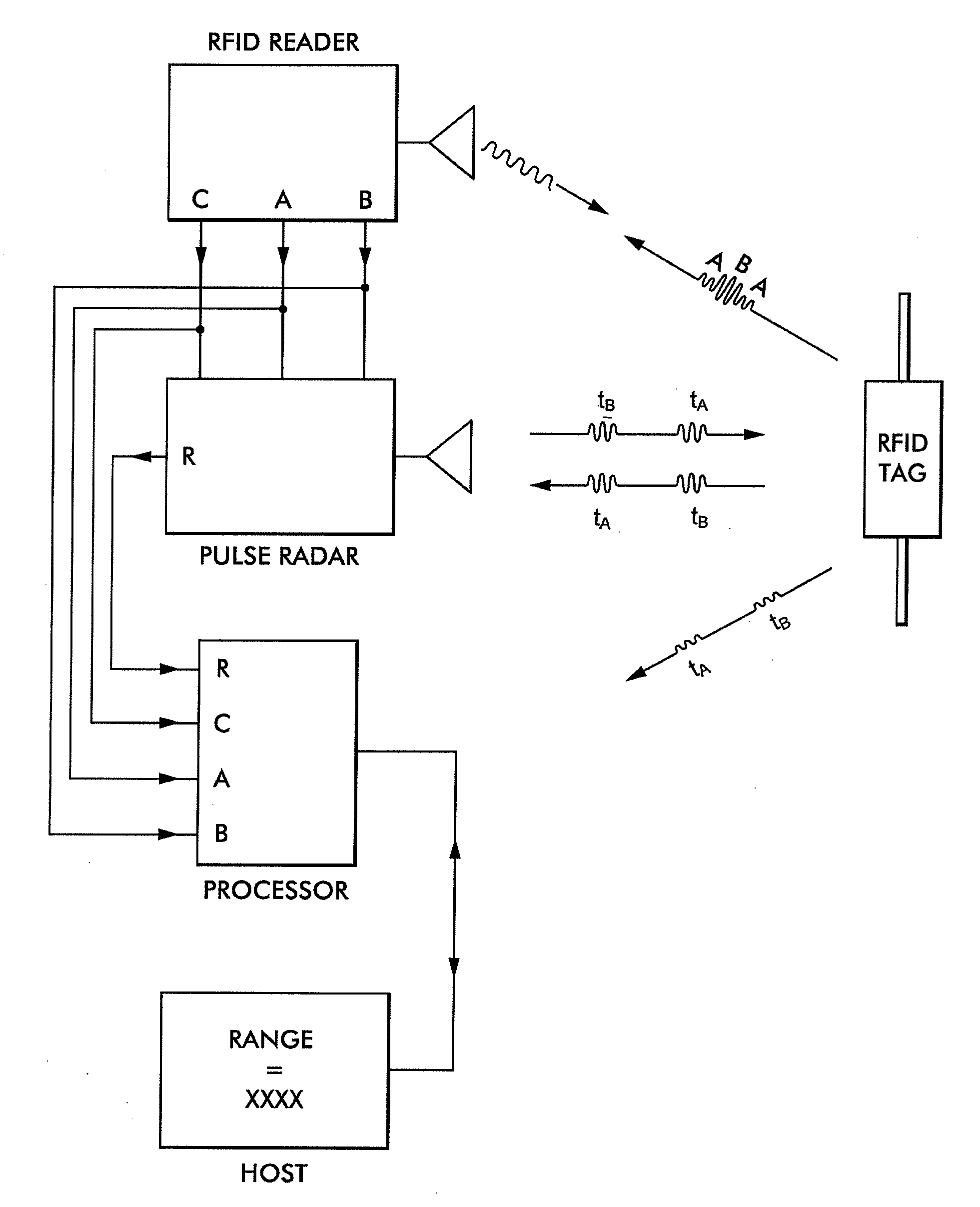
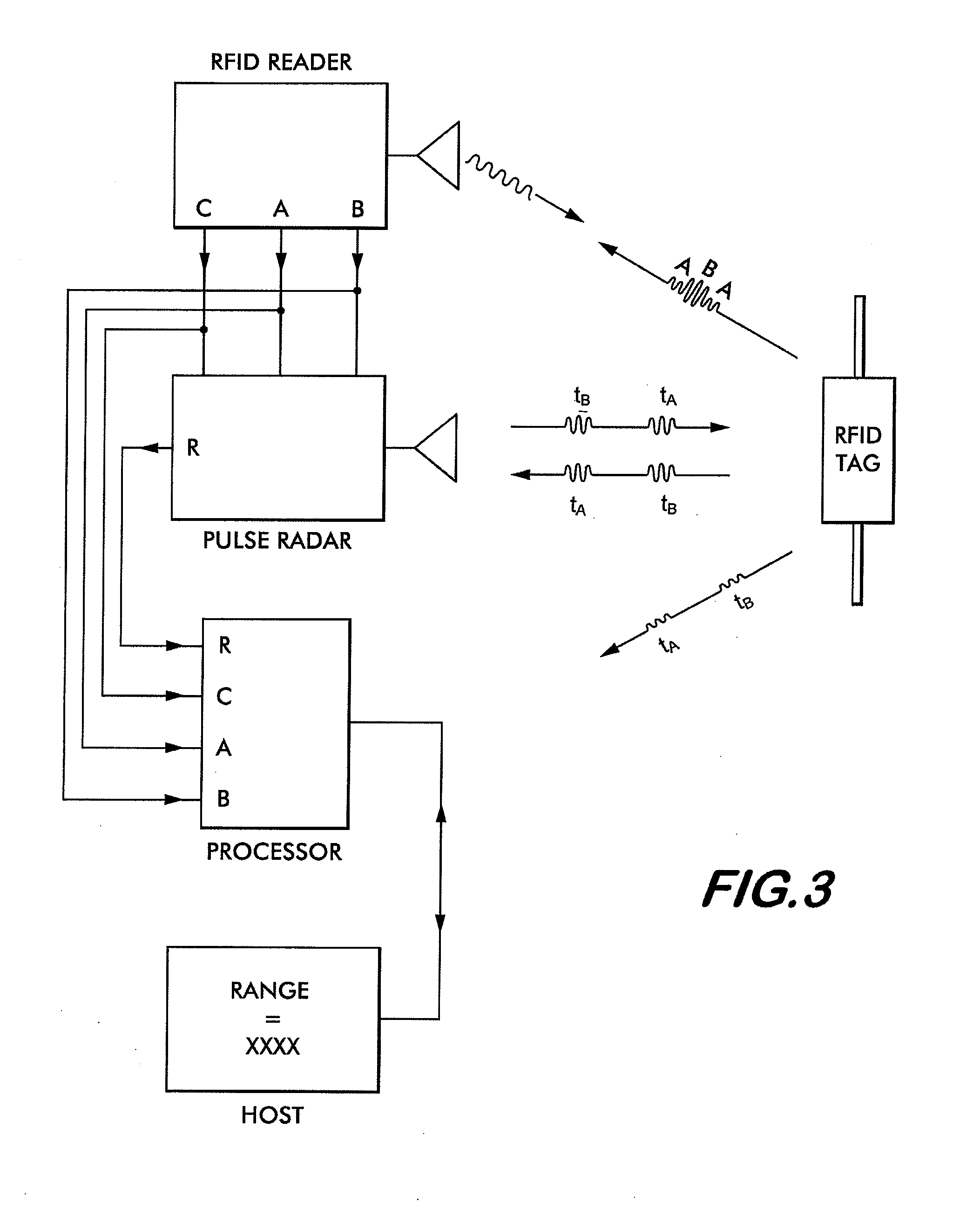
[0119]Methods shown in Example 1 and Example 2 illustrate the technique of differential pulse compression radar to measure the distance to a tag in the presence of clutter and multipath. Example 2 also shows the ability of the methods to suppress amplitude noise as shown in FIG. 6b through FIG. 6g. Implementation of the methods are improved by consistency in timing, frequency and amplitude and minimizing jitter of the transmitted radar pulses and subsequent data processing. An improved differential pulse compression radar is shown in FIG. 7. The RFID Reader, Host and data processing sections of FIG. 3 have been omitted for clarity.

[0120]Operation is performed using a minimum set of signals. First, timing is derived from a signal (from a reader or other source) indicting the modulation state of the tag being read. An example of such a signal is the “TAG MODULATION STATE” of FIG. 4 and “Modulation State from Reader” on FIG. 7. Further referring to FIG. 7, Signal Generator 1 (Agilent M...

example 1

OFDM Example 1

[0135]The first OFDM example uses the ‘short training sequence’ symbol of IEEE Std 802.11-2007 Paragraph 17.3.3 equation 17-6 (also known as IEEE 802.11a). This OFDM symbol contains 12 subcarriers spaced 1.25 MHz apart. For illustration of the invention, the subcarriers are up converted by 65 MHz resulting in subcarriers from 57.5 MHz to 72.5 MHz with the center subcarrier missing (at 65 MHz). This signal could be used as the output of the arbitrary waveform generator ARB 2 (or equivalent) in FIG. 8. This band is the chosen intermediate frequency (IF) band for this example. An actual 802.11a system would further up convert the signals to the chosen band in the UNII service (a 5.8 GHz band) for transmission and reception. An RFID system would further up convert to the desired band such as from 907.5 MHz to 922.5 MHz centered at 915 MHz with the frequency of the Signal Generator 1 at the chosen 850 MHz in FIG. 8.

[0136]The short training sequence symbol repeats in 800 nan...

example 2

OFDM Example 2

[0139]The second OFDM example uses a Barker code to set the phase on each of 13 subcarriers. Barker codes have unique correlation properties and are often used in digital communication systems. The phase of each subcarrier was set to 90 degrees or −90 degrees depending on the Barker code. The 13 element Barker code is +1+1+1+1+1−1−1+1+1−1+1−1+1. The frequency separation was set to 2 MHz and the IF center frequency to 65 MHz. The resulting IF bandwidth is from 53 MHz to 77 MHz. When further upconverted by 850 MHz, the transmitted signals are in the range from 903 MHz to 927 MHz.

[0140]The signal strength varies little throughout the period of the signal as shown by the magnitude of the IF signal in FIG. 12a. The signal repeats in at a period of 500 ns in an alternating fashion. Thus, the particular signals of this example have a range multiplicity for delays greater than 500 ns, or a range greater than about 250 feet. The magnitude of the FFT of the IF signal is shown in...


PUM


Abstract

A system for measuring range to an RFID tag including situations containing high clutter and multi-path signals is disclosed. The system includes an RFID reader; an RFID tag; and a coordinated signal compression radar system. The reader causes the tag to respond to received signals in a first backscatter state at a first time and a second backscatter state at a second time. The signal compression radar system transmits signals coordinated by the backscatter state of the tag and creates a differential signal comprised of the differences between radar signals obtained during the first and second states of the tag to obtain an uncorrupted measure of a round trip time of flight of said radar signals between the radar system and the RFID tag. The radar may use signals typical of pulse compression radar systems such as chirp modulation or Orthogonal Frequency Domain Modulation (OFDM), either pulsed or semi-continuous.

Description

CROSS-REFERENCE TO RELATED APPLICATIONS[0001]This utility application claims the benefit under 35 U.S.C. §119(e) of Provisional Application Ser. No. 61 / 355,824, filed on Jun. 17, 2010, entitled System and Method for Microwave Ranging to a Target in Presence of Clutter and Multi-path Effects, also claims benefit under 35 U.S.C. §120 as a continuation-in-part of Utility application Ser. No. 13 / 095,296 filed on Apr. 27, 2011, also entitled System and Method for Microwave Ranging to a Target in Presence of Clutter and Multi-path Effects, and also Utility application Ser. No. 13 / 163,005 filed on Jun. 17, 2011, also entitled System and Method for Microwave Ranging to a Target in Presence of Clutter and Multi-path Effects. The entire disclosures of these applications are incorporated by reference herein.FIELD OF INVENTION[0002]This invention relates to the field of electromagnetic distance measurement and, in particular, distance measurement to an RFID device.BACKGROUND OF THE INVENTION[00...

Claims


Application Information

Patent Timeline
IPC IPC(8): G01S13/32
CPCG01S7/023G01S13/765G01S13/751G01S7/0232
Inventor GRAVELLE, KELLYLANDT, JEREMYLUNSFORD, PATRICK W.
Owner AMTECH SYST
Why Eureka
Try Eureka