
Switching a PLL Clock Source to Reduce Wireless Communication Interference

Active Publication Date: 2012-05-24
APPLE INC
View PDF1 Cites 22 Cited by
  • Summary
  • Abstract
  • Description
  • Claims
  • Application Information

AI Technical Summary

Benefits of technology

[0007]Once aligned, the clock signals provided to the PLL may be switched from the first clock to the second clock. Since the clock signals are aligned, the switching may not cause a loss of lock by the PLL. The alignment and switchover described above may be controlled by a state machine. Additionally, the alignment may be enabled using an enable bit, e.g., which may be set based on software executing on the wireless device.
[0008]As indicated above, the second clock may be an adjustable or modulated (e.g., dithered) clock which causes the serial interface clock to have a lower interference than when using the first, static clock.
[0010]In further embodiments, the source of the first clock frequency information may be more elaborate. For example, the first clock frequency information may be based on the information stored in the register, but may be modified by an oscillator. For example, the oscillator may modulate the information stored in the register to produce the first clock frequency information. In some embodiments, instead of a register specifying the clock frequency information, a table of information may be used. For example, the table may store multiple different divisors that may be selectable for provision as the first clock frequency information. Similar to above, this information may be modulated by the oscillator. Further, the oscillator may control a counter that may be used to select the information from the table that is then modulated by the oscillator and provided as the first clock frequency information. In embodiments using the oscillator, the second clock may be a spread spectrum clock that spreads its frequency and harmonics enough that interference of the wireless channels are mitigated without having to specifically change the frequency of the clock based on the wireless channels in use (or future use). Thus, in these embodiments, the clock may be constantly modulated rather than being repeatedly programmed.
[0012]The first clock frequency information may be modified to produce second clock frequency information. For example, the first clock frequency information may be modified by a filter (e.g., a low pass filter). In more detail, the first clock frequency information may specify a clock frequency (e.g., the first clock frequency) that is different from the current clock frequency that is being provided by the second clock. Accordingly, the first clock frequency information may be modified to the second clock frequency information in a manner that prevents the PLL from losing lock in response to the changing clock frequency of the second clock. The first clock frequency information may be modified using transition information (e.g., which may be stored in a register). The transition information may limit the amount of change of the current clock frequency in a manner that allows the PLL to retain lock. For example, the transition information may define a slope for changing the current clock frequency to that specified by the first clock frequency information.
[0013]The second clock information may be modified to produce a divisor. For example, the second clock information may be modified by a modulator, such as a sigma delta circuit. Finally, the second clock may receive a higher frequency clock signal and divide that higher frequency clock signal by the divisor to produce the second clock signals. These second clock signals may be provided to the PLL and may mitigate wireless communication interference by changing the clock signals provided by the serial interface.

Problems solved by technology

The serial output clock (e.g., harmonics of the clock) may interfere with wireless communication channels used during wireless communication.
However, such a clock may not be available at all times, so it may also be desirable to switch from driving the PLL with a first clock (e.g., a static clock) to a second clock (e.g., a modulated or programmable clock).
More particularly, at a first time, the first clock may be available, but the second clock may not be available.
However, the first clock and second clock may not be aligned when the second clock becomes available.

Method used


Image

  • Switching a PLL Clock Source to Reduce Wireless Communication Interference
  • Switching a PLL Clock Source to Reduce Wireless Communication Interference
  • Switching a PLL Clock Source to Reduce Wireless Communication Interference

Examples


second embodiment

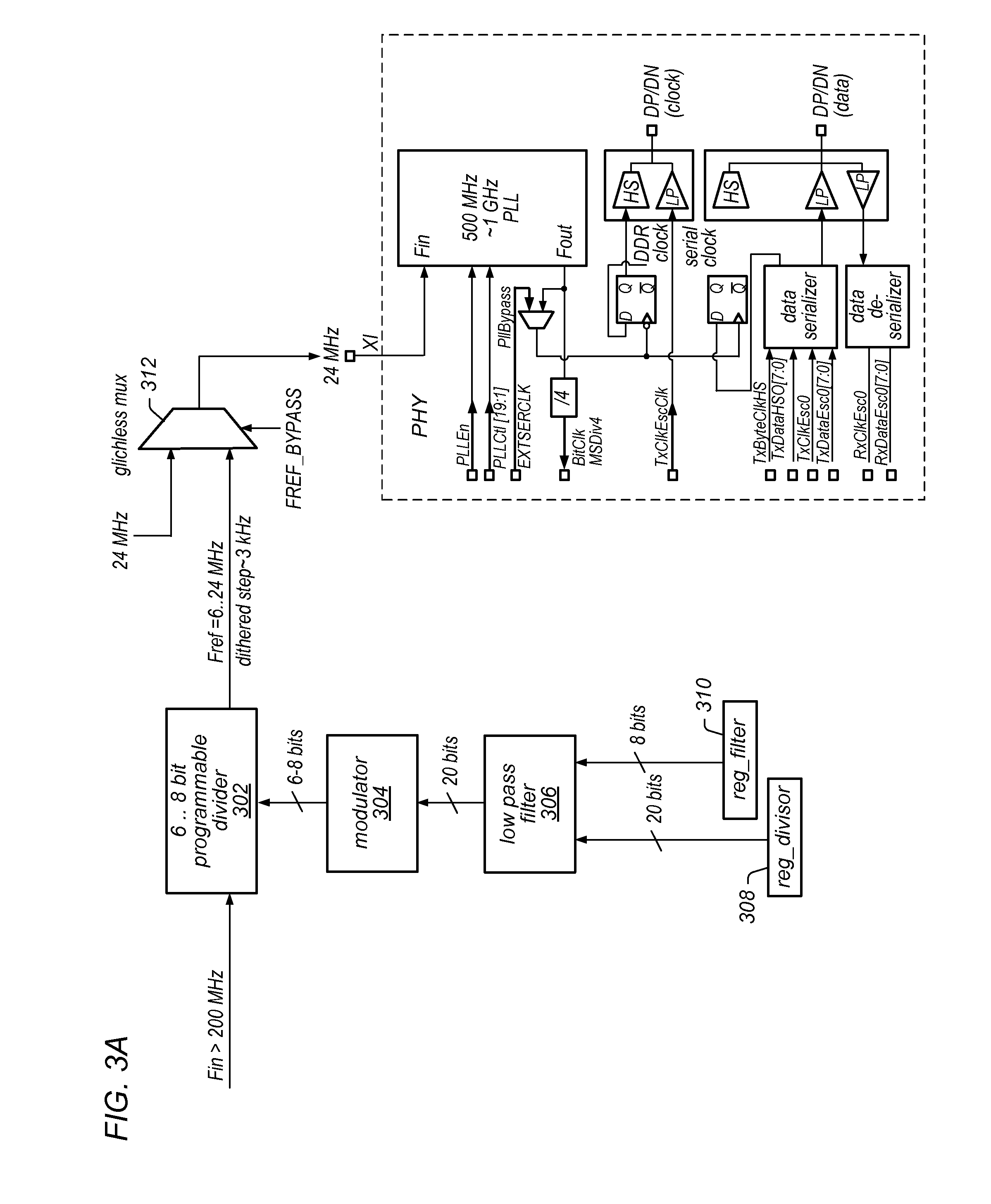
[0038]FIG. 3B illustrates a second embodiment, which operates similarly to FIG. 3A. However, as shown in FIG. 3B, a digital oscillator 320 is added to the reg_divisor 308 as input to the low pass filter 306. The digital oscillator 320 may receive a period and gain from reg_period 322 and reg_gain 324 to control the oscillator's output. By adding the digital oscillator 320, the divisor provided to the low pass filter changes over time, which results in the frequency of the HSSI clock varying over time. Accordingly, the harmonics of the HSSI clock may be spread among a wider frequency range and therefore lessen the strength of interference within wireless communication channel(s).

third embodiment

[0039]FIG. 3C illustrates a third embodiment, which operates similarly to FIG. 3B. However, as shown in FIG. 3C, instead of using reg_divisor 308, a table (e.g., a 16 entry table) may be used for specifying different frequencies. Similar to FIG. 3B, the selected divisor from this table may be added to the output of the digital oscillator as input to the low pass filter 306. The entry from the table may be selected by the counter 332, whose value may be modified according to the digital oscillator 320 (e.g., the carry from the digital oscillator 320).

[0040]FIGS. 5A-5D illustrate exemplary oscillator outputs and resulting clock output power levels. As shown, a sinusoidal oscillator output results in a power output that is concave in between two peaks. A triangular oscillator output results in lower peaks and more constant power output level. FIG. 5C illustrates a cubic oscillator output with a power output that is similar (but marginally better) than the triangular wave of FIG. 5C. Fi...


PUM


Abstract

Adjusting a phase locked loop (PLL) clock source to reduce wireless communication (e.g., radio frequency (RF)) interference within a device. The PLL may be included in a high speed serial interface, e.g., coupled to a display, and may be initially driven by a first clock. Later, when a second clock is available and aligned with the first clock, the PLL may be driven by the second clock. The second clock may be configured to change its frequency over time such that the PLL does not lose lock and also does not interfere (or reduces interference) with wireless communication of the device. For example, the second clock may be programmable or may dynamically vary its operating frequency, thereby reducing its interference with the wireless communication of the device.

Description

FIELD OF THE INVENTION[0001]The present invention relates to the field of computers, and more particularly a system and method for adjusting a phase locked loop (PLL) clock source to reduce wireless communication interference.DESCRIPTION OF THE RELATED ART[0002]Modern electronic devices include clocking signals which are used to keep various components of the device in sync. However, in some mobile devices, e.g., mobile phones, the clocking signals may cause interference within a wireless communication channel. This is often exacerbated by the fact that the mobile device will often have to use different communication channels to communicate with different devices and / or according to different communication standards. As a result, there may not be a single “safe” frequency in which the clock can operate. Accordingly, improvements in clocking signals within devices are desired.SUMMARY OF THE INVENTION[0003]Various embodiments are presented of a system and method for changing and adjus...

Claims


Application Information

Patent Timeline
IPC IPC(8): G09G5/00H03L7/08
CPCH04B15/06
Inventor FRANK, MICHAEL
Owner APPLE INC
Features
  • Generate Ideas
  • Intellectual Property
  • Life Sciences
  • Materials
  • Tech Scout
  • Unparalleled Data Quality
  • Higher Quality Content
  • 60% Fewer Hallucinations
Learn More