Method and device to securely open and close a passageway or access point

a technology of access point, which is applied in the field of sensor devices, can solve the problems of unscrupulous activation, false activation of doors, and inability to secure the passageway or access point, and achieve the effect of low transmissivity and high transmissivity

Inactive Publication Date: 2012-05-24
BEA INC
View PDF4 Cites 69 Cited by
  • Summary
  • Abstract
  • Description
  • Claims
  • Application Information

AI Technical Summary

Benefits of technology

[0013]According to another embodiment of the present invention, the active infrared sensor device may further include one or more optical elements in the path of the at least one infrared emitter or the at least one infrared receiver. The optical elements may have high transmissivity to infrared radiation and low transmissivity to radiation outside the infrared spectrum.

Problems solved by technology

PIR devices are susceptible to false activation, activation by unscrupulous activity, or activation by thermal changes near a passageway.
Pedestrian traffic passing by a passageway controlled by the PIR device often leads to false activation of the door.
Even after adjusting the PIR device to minimize its activation zone, false door activations can still arise due to any of the above-identified factors.
Furthermore, it is common practice to place heating and cooling devices near doorways, which can further complicate the problem of false activations by affecting the thermal sensitivity of the PIR device.
An additional drawback of conventional PIR devices is their susceptibility to false activation and / or inoperation due to electromagnetic interference.
This may lead to electromagnetic interference that in turn may lead to a failure of electronic devices that share the same circuit with the automatic door mechanism.
These additional features lead to increased cost for manufacturing and / or installing the PIR device.

Method used


Image

  • Method and device to securely open and close a passageway or access point
  • Method and device to securely open and close a passageway or access point
  • Method and device to securely open and close a passageway or access point

Examples


Embodiment Construction

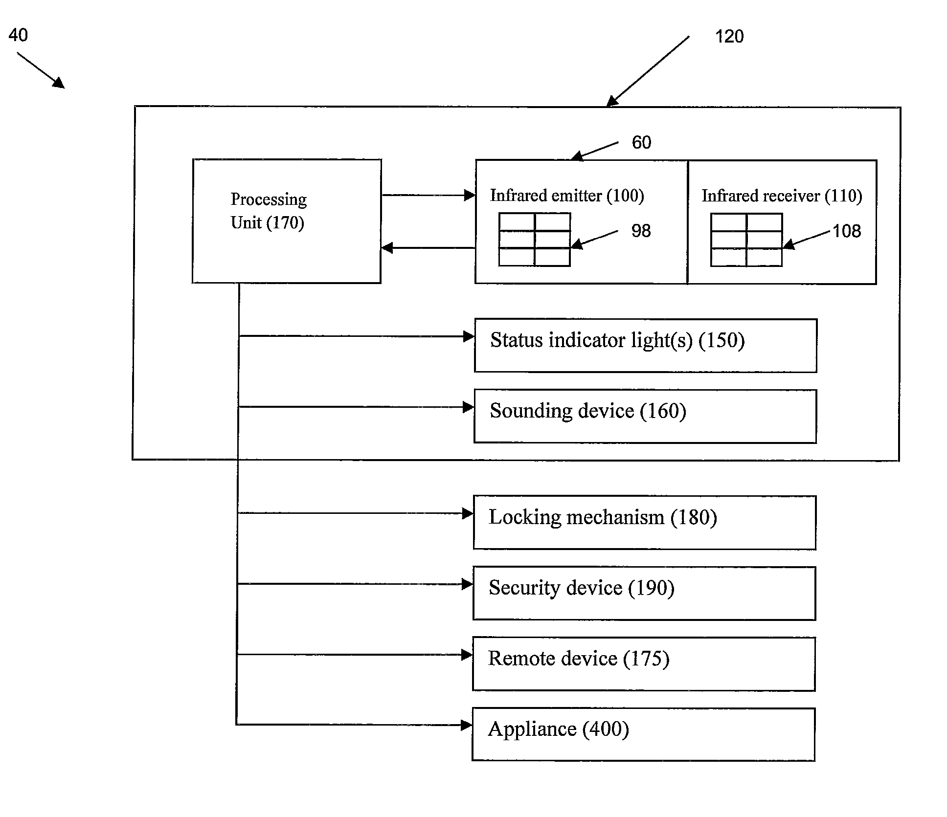
[0030]Referring to the drawings in which like reference characters refer to like parts throughout the several views thereof, the present invention is generally described in terms of a device and a method applicable to security doors wherein a request to exit or enter a secure side of a door is determined by sensing for the presence of an object, such as a person's hand, within a surveillance area. Within the present disclosure, the term “signal”, whether or not used in combination with a descriptive label such as “optical” or “electrical”, means any quantity measurable through time or over space, where such quantity is capable of being emitted by an object or component or received by the same.

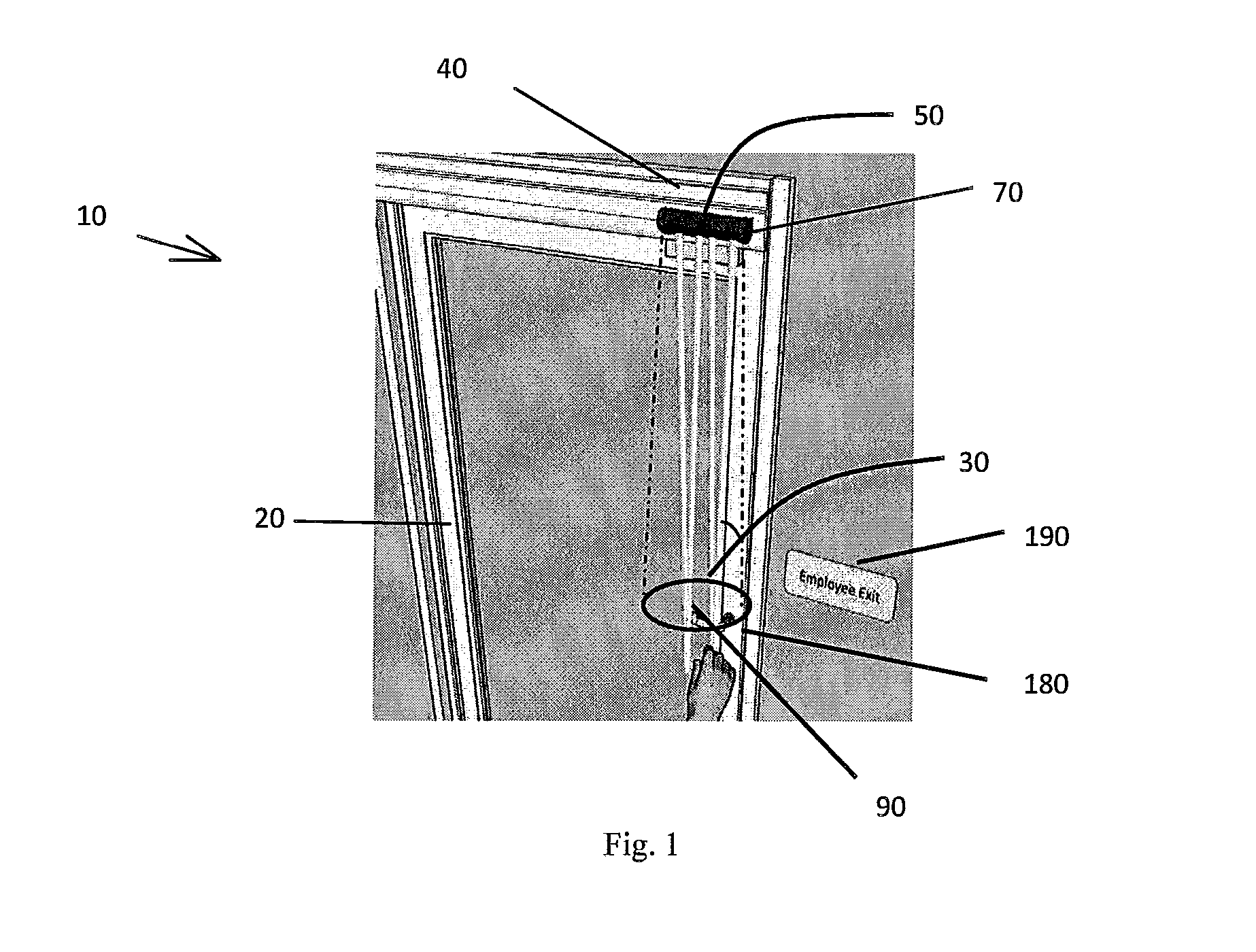
[0031]FIG. 1 is a front perspective view of a passageway access control system 10 according to an embodiment of the present invention. System 10 opens and closes, or unlocks and locks, a passageway barrier, such as a door 20, formed through a passageway. Door 20 is illustrated in FIG. 1 as a sw...


PUM


Abstract

An access control system for a passageway having a passageway barrier including an active infrared sensor device and a locking mechanism for selectively locking and unlocking the passageway barrier. The active infrared sensor device includes an infrared emitter, an infrared receiver having one or more position-sensing photodetectors operative for receiving infrared light and generating a signal corresponding to a position and/or intensity of the reflected infrared light, and a processing unit operative for detecting a change between a first signal generated by one or more position-sensing photodetectors after receiving reflected infrared light at a first location on one or more position-sensing photodetectors and a second signal generated by one or more position-sensing photodetectors after receiving infrared light reflected in response to the object moving into the surveillance area and for controlling an operation of a locking mechanism based on the change.

Description

CROSS-REFERENCE TO RELATED APPLICATION[0001]This application claims priority to U.S. Provisional Patent Application No. 61 / 415,511, filed Nov. 19, 2010, entitled “Method and Device to Securely Open and Close a Passageway or Access Point”, the entire disclosure of which is herein incorporated by reference.BACKGROUND OF THE INVENTION[0002]1. Field of the Invention[0003]This invention relates, in general, to a sensor device, and more particularly, to a sensor device especially applicable for security doors wherein a request to exit or enter a secure side of a door is determined by sensing for the presence of an object, such as a person's hand, within a surveillance area.[0004]2. Description of the Related Art[0005]Motion sensors are commonly utilized to detect presence and motion within a surveillance area. Such sensors may be used in a variety of applications, including door sensor devices particularly adapted to detect a presence of an object near a passageway or an access point. In ...

Claims


Application Information

Patent Timeline
Patent Type & Authority Applications(United States)
IPC IPC(8): H04N7/18
CPCG08B13/08G08B13/183G08B13/19695E05F15/00G01V8/14E05F2015/765E05Y2201/68E05Y2400/852E05Y2400/822E05F15/73E05Y2400/86E05B2047/0056
Inventor YANTEK, THOMAS MICHAELCRADDOCK, TIMOTHY U.GIANETTINO, ANTHONY KENNETHMULCAHY, JOSEPH MARKWICKMAN, RANDY WILLIAM
Owner BEA INC
Why Eureka
Try Eureka