
Method and System for Display Characterization or Calibration Using A Camera Device

a technology of display device and camera device, which is applied in the field of method and system for display device characterization or calibration, to achieve the effect of accurate characterization of display device and removal of much uncertainty

Active Publication Date:
View PDF11 Cites 85 Cited by
  • Summary
  • Abstract
  • Description
  • Claims
  • Application Information

AI Technical Summary

Benefits of technology

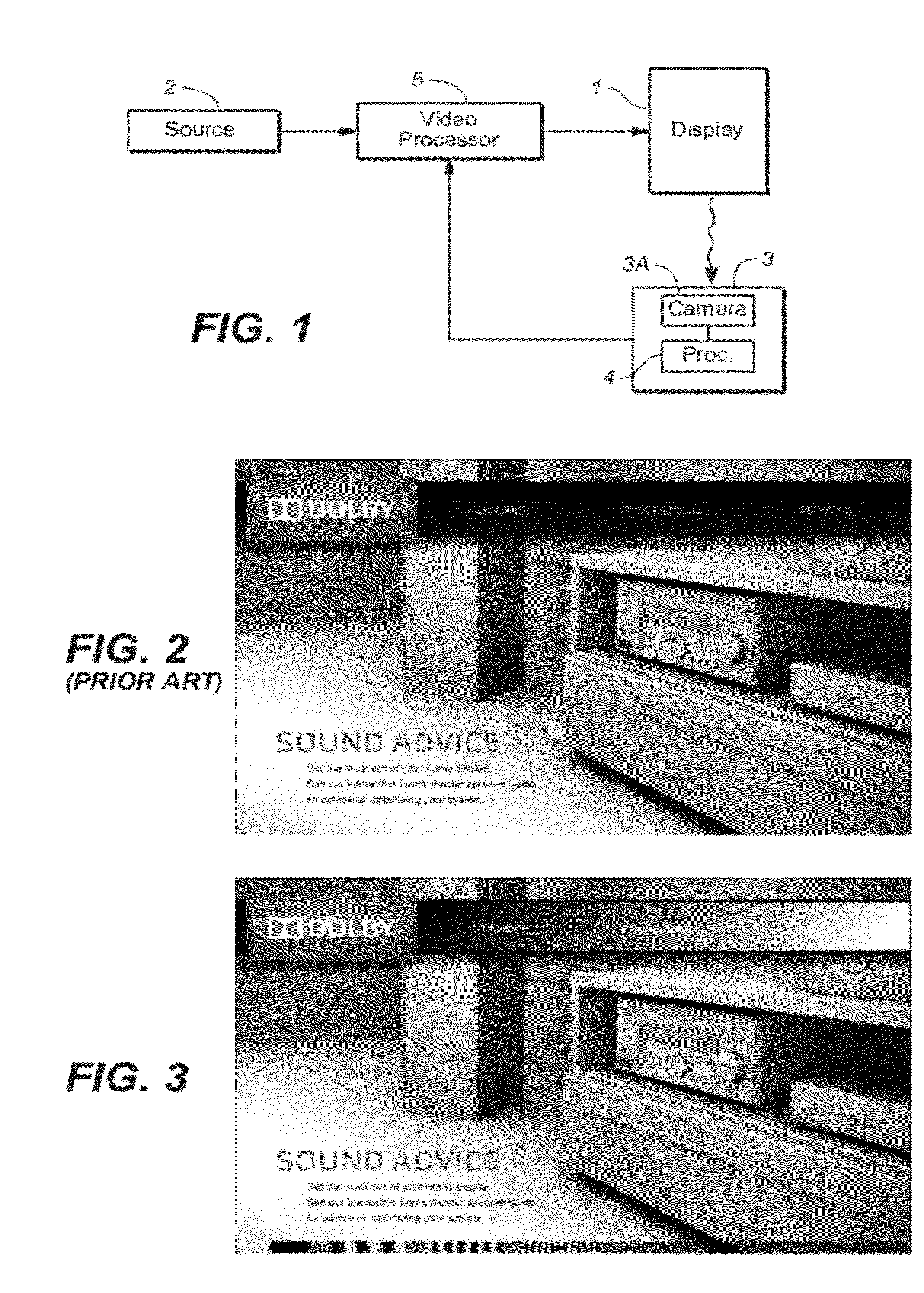
[0023]the test images are “watermarked” or otherwise augmented versions of arbitrary video images. A conventional sequence of arbitrary video images (frames) generally lacks sufficient diversity to allow adequate display characterization or calibration. Some simple modifications of conventional video frames to include test image content therein include contrast range expansion and embedded watermarks. Such a modification, along with knowledge of the modification by the analysis tool, typically suffices to achieve accurate calibration and / or characterization. The simplest form of achieving suitable calibration stimulus is to introduce diversity in proximate pixels of each conventional (unmodified) arbitrary frame, in such a way as to allow testing of the display device range without destroying the intended (unmodified) image content. This can be done by introducing a form of modulated dither that adds test image content.
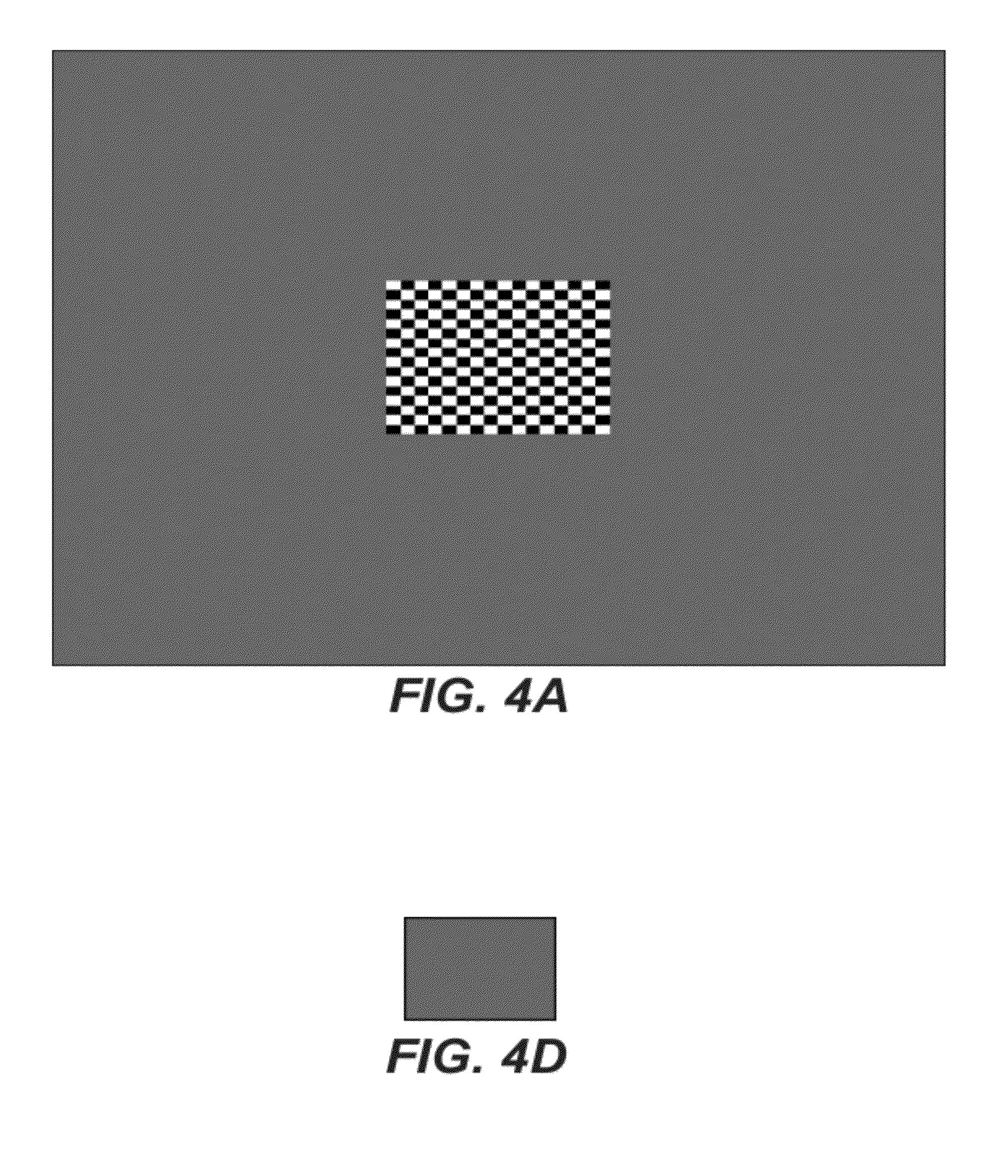
[0026]Preferably, a test image displayed on the display device to be characterized includes a “first” guide (e.g., a distinctive pattern), and another guide (a “second” guide) is generated by the camera device and presented to the user on the camera device's display screen. The user can align the camera device's camera with the display device by moving the camera device so that the second guide matches the first guide on the camera device's display screen. So aligning the first guide with the second guide can achieve very accurate and repeatable positional alignment of the camera with the display device. The edges of each test image displayed by the display device are preferably expendable, in the sense that they are designed such that small variations (e.g., zoom or crop variations) in the camera's field of view do not lead to significant changes in the overall lux detected by the camera (e.g., to avoid AGC variations) when the camera is at least roughly aligned with the display device.
[0030]The appropriate choice of test image(s) and analysis of each test image can remove much uncertainty that would otherwise result from unknown camera parameters, to allow at least some types of reliable display device assessment and calibration using the output of a camera device (even an uncalibrated camera device). For example, in some embodiments the test images displayed by a display device are chosen to allow accurate characterization of the display device using a camera device but without knowledge of at least some characteristics of the camera device's camera.

Problems solved by technology

The adjustment of a video display for optimal picture quality, and the general assessment of displayed image quality and display device characteristics is a challenging task, generally thought to be well outside an average consumer's capabilities.

Method used


Image

  • Method and System for Display Characterization or Calibration Using A Camera Device
  • Method and System for Display Characterization or Calibration Using A Camera Device
  • Method and System for Display Characterization or Calibration Using A Camera Device

Examples


Embodiment Construction

[0060]Many embodiments of the present invention are technologically possible. It will be apparent to those of ordinary skill in the art from the present disclosure how to implement them. Embodiments of the inventive system and method will be described with reference to FIGS. 1 and 3-6.

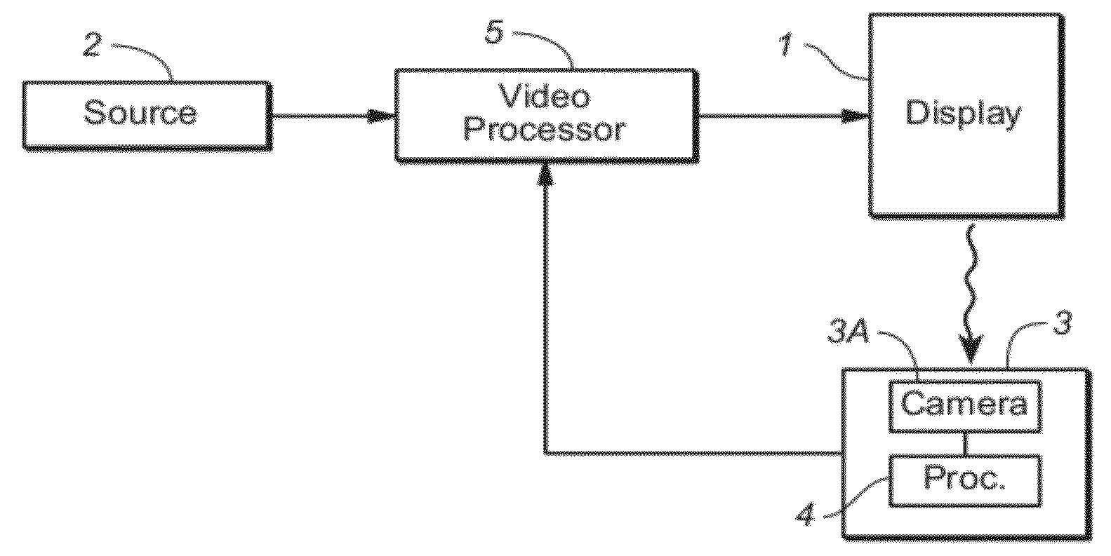
[0061]FIG. 1 is a block diagram of an embodiment of the inventive system. The system of FIG. 1 includes display device 1 configured to display images sequentially in response to a video input signal from source 2. Display device 1 may be implemented as any of a variety of display devices, (e.g., a standard LED or LCD display, or another display device).

[0062]Video processor 5 is coupled and configured to receive a video input signal from source 2, to perform required processing thereon to generate a video signal for display on device 1, and to assert a video signal to display device 1 for driving the pixels of display device 1. In cases in which display device 1 includes a backlighting or edge-lighting...


PUM


Abstract

In a class of embodiments, a method and system for characterizing a display device using a camera device (e.g., a consumer grade, mobile camera device) to sense light emitted by the display device during display of one or more test images, and to generate measurement data characterizing the display and / or calibration data useful for calibrating the display device. In some embodiments, the display device is adjusted or calibrated manually in response to such calibration data, for example by user actuation of display device controls in response to calibration data indicative of display setting recommendations. In some embodiments, the test image(s) are embedded in a video stream (e.g., overlaid on arbitrary video content). For example, test images including appropriate timing information and calibration sequences are embedded in a video stream for display by the display device. In some embodiments, the user is prompted to align the camera device (e.g., to position the camera device such that light emitted from a test image at least substantially fills the camera field of view).

Description

BACKGROUND OF THE INVENTION[0001]1. Field of the Invention[0002]Some embodiments of the invention are systems and methods for characterizing a display using a camera device (e.g., a handheld or other mobile camera device) to measure light emitted by the display, and optionally also to calibrate the display using control parameters determined using measurements of the light by the camera device.[0003]2. Background of the Invention[0004]Throughout this disclosure including in the claims, the expression performing an operation “on” signals or data (e.g., filtering the signals or data) is used in a broad sense to denote performing the operation directly on the signals or data, or on processed versions of the signals or data (e.g., on versions of the signals that have undergone preliminary filtering prior to performance of the operation thereon).[0005]Throughout this disclosure including in the claims, the expression “system” is used in a broad sense to denote a device, system, or subsys...

Claims


Application Information

Patent Timeline
Patent Type & Authority Applications(United States)
IPC IPC(8): H04N17/00
CPCG09G3/006G09G2360/145G09G2320/0693H04N17/04
Inventor DICKINS, GLENNARIDIS-LANG, SIMON
Learn More