
Radiation phase image obtainment method and radiation phase image radiographic apparatus

a radiographic apparatus and radiation phase technology, applied in the direction of instruments, diaphragms, radiation diagnostic devices, etc., can solve the problems of inability to obtain sufficient contrast in an image, inability to obtain x-ray transmission images with sufficient intensity (contrast), and small difference in x-ray absorption between the two

Inactive Publication Date: 2012-05-24
FUJIFILM CORP
View PDF0 Cites 19 Cited by
  • Summary
  • Abstract
  • Description
  • Claims
  • Application Information

AI Technical Summary

Benefits of technology

[0039]According to the radiation phase image obtainment method and the radiation phase image radiographic apparatus of the present invention, an input of a magnification ratio in magnification radiography is received, and calibration data corresponding to the received magnification ratio, and which are based on a second periodic pattern image detected by a radiation image detector without placing a subject are obtained. Further, a phase contrast image is obtained based on the obtained calibration data and the second periodic pattern image detected by the radiation image detector with the subject placed. Therefore, even if the distribution of doses of radiation at the radiation image detector, a phase offset, and a phase sensitivity change by magnification radiography, appropriate calibration for each magnification radiography is possible. Hence, it is possible to obtain appropriate phase contrast images.

Problems solved by technology

Since a difference in X-ray absorptivity is small in soft tissue of a living body, soft material, and the like, a sufficient difference in intensity (contrast) as an X-ray transmission image is not obtainable.
Therefore, a difference in X-ray absorptivity between the two is small, and a sufficient contrast in an image is hard to obtain.
However, for example, in correction of the distribution of doses of radiation, appropriate correction is not possible if the same correction data are used for magnification radiography at various magnification ratios, because the distribution of doses of radiation differs depending on the magnification ratios.
Therefore, if the same calibration data are uniformly used to generate phase contrast images, it is impossible to generate an appropriate phase contrast image at some magnification ratio.
However, Patent Document 1 is silent about the aforementioned problems, and fails to propose any solution for solving the problems.

Method used


Image

  • Radiation phase image obtainment method and radiation phase image radiographic apparatus
  • Radiation phase image obtainment method and radiation phase image radiographic apparatus
  • Radiation phase image obtainment method and radiation phase image radiographic apparatus

Examples


Embodiment Construction

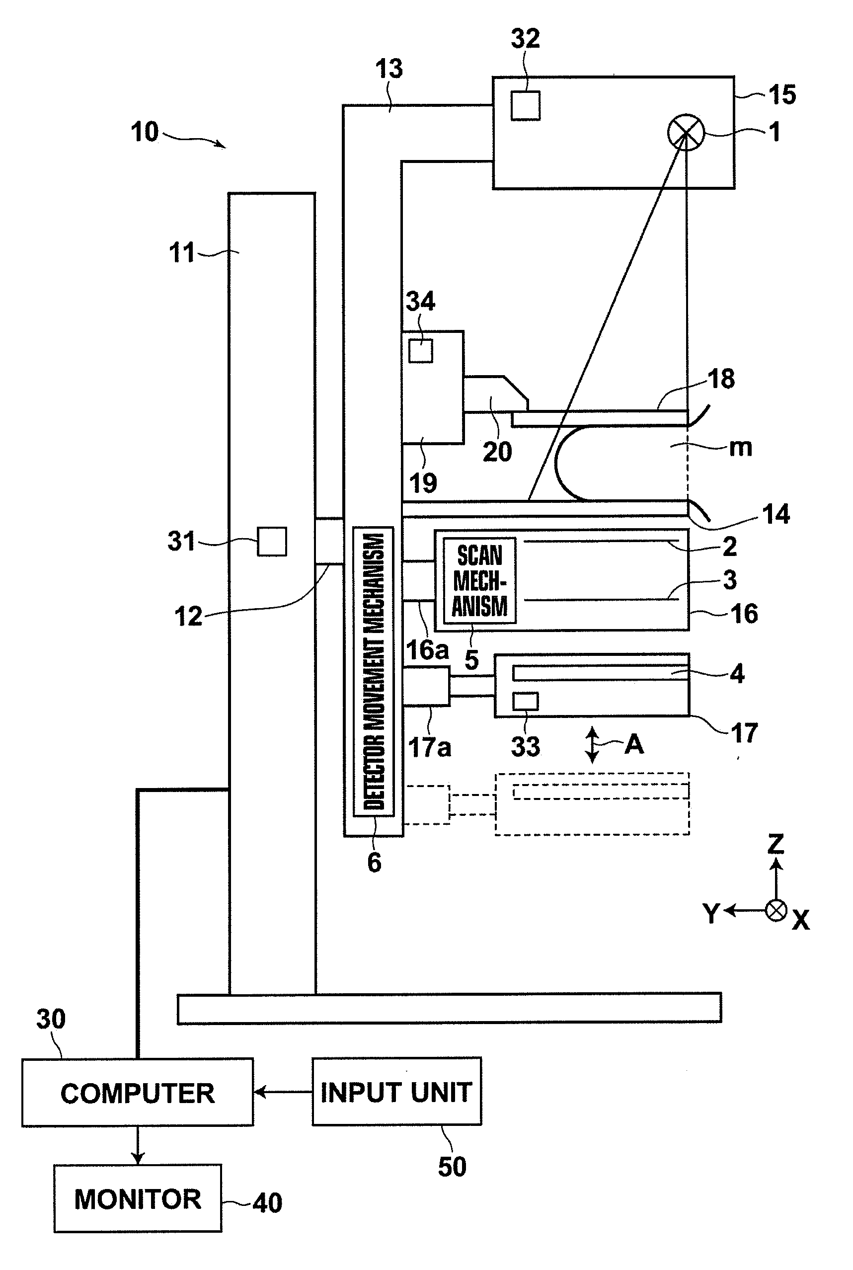
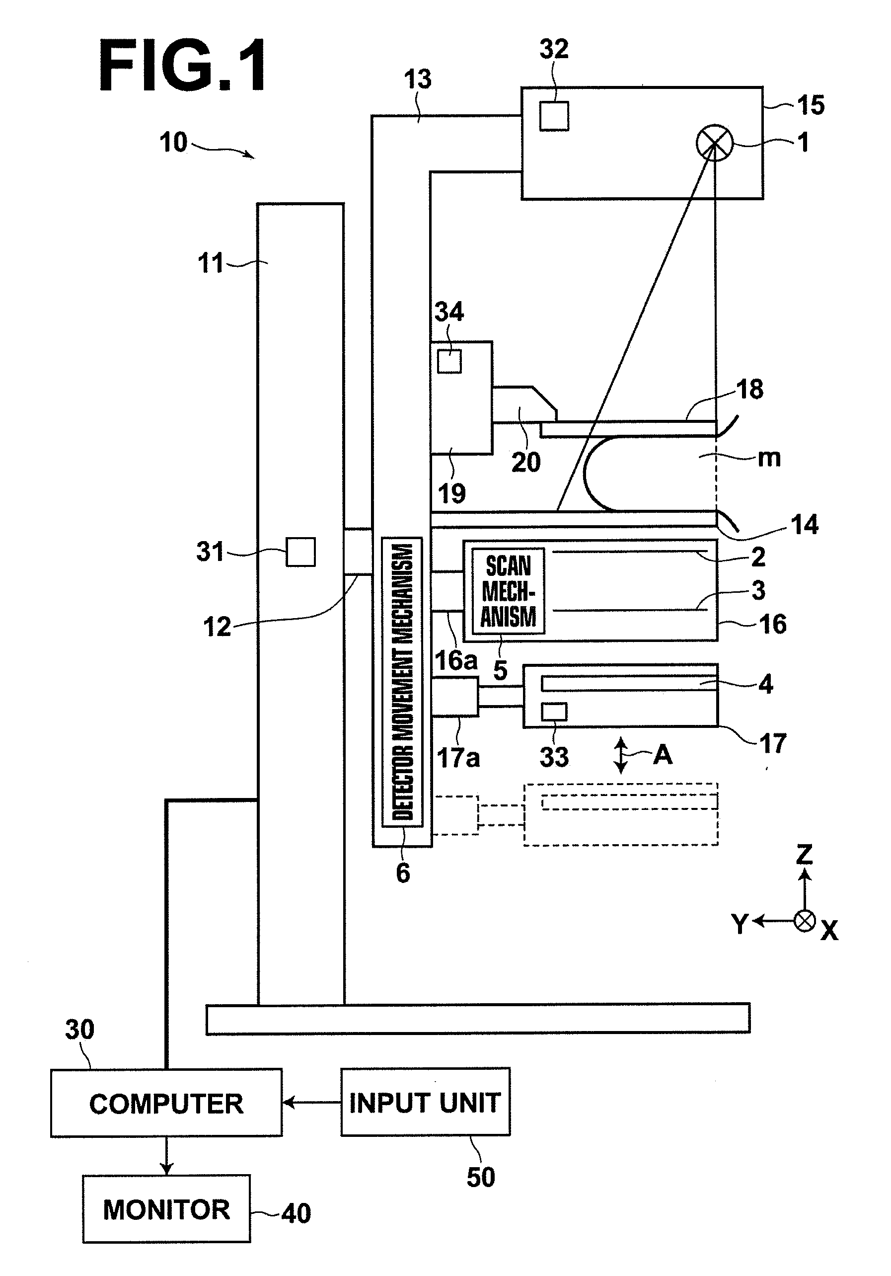
[0075]Hereinafter, a mammography and display system using an embodiment of a radiation phase image radiographic apparatus according to the present invention will be described with reference to drawings. FIG. 1 is a schematic diagram illustrating the configuration of the whole mammography and display system using an embodiment of the present invention.

[0076]As illustrated in FIG. 1, the mammography and display system of the present invention includes a mammography apparatus 10, a computer 30 connected to the mammography apparatus 10, a monitor 40 connected to the computer 30, and an input unit 50.

[0077]As illustrated in FIG. 1, the mammography apparatus 10 includes a base 11, a rotation shaft 12, and an arm 13. The rotation shaft 12 is movable in a vertical direction (Z direction) with respect to the base 11, and rotatable. The arm 13 is connected to the base 11 by the rotation shaft 12.

[0078]The arm 13 is alphabet “C” shaped. A radiography table 14 on which breast m is to be set is ...


PUM


Abstract

In a radiation phase image radiographic apparatus, a radiation image detector detects a periodic pattern image that has passed through a first grating and a second grating. The apparatus includes a magnification ratio obtainment unit that receives an input of a magnification ratio in magnification radiography to obtain the magnification ratio, a movement mechanism that moves, based on the magnification ratio, the radiation image detector relative to a subject in a direction away from the subject, a calibration data obtainment unit that obtains calibration data corresponding to the magnification ratio, and which are based on the periodic pattern image detected by the radiation image detector without placing the subject, and a phase contrast image generation unit that generates a phase contrast image based on the calibration data and the periodic pattern image detected by the radiation image detector with the subject placed.

Description

BACKGROUND OF THE INVENTION[0001]1. Field of the Invention[0002]The present invention relates to a radiation phase image obtainment method and a radiation phase image radiographic apparatus using a grating or gratings. In particular, the present invention relates to a radiation phase image obtainment method and a radiation phase image radiographic apparatus in which magnification radiography is performed.[0003]2. Description of the Related Art[0004]Since X-rays attenuate depending on the atomic number of an element constituting a substance through which the X-rays pass, and the density and the thickness of the substance, the X-rays are used as a probe for observing the inside of a subject from the outside of the subject. Radiography using X-rays is widely used in medical diagnosis, non-destructive examination, and the like.[0005]In a general X-ray radiography system, a subject is placed between an X-ray source for outputting X-rays and an X-ray image detector for detecting an X-ray ...

Claims


Application Information

Patent Timeline
IPC IPC(8): G01N23/04
CPCA61B6/06A61B6/4291A61B6/484A61B6/588A61B6/547A61B6/582A61B6/502
Inventor ISHII, HIROYASU
Owner FUJIFILM CORP
Learn More