Rotor section for a rotor of a turbomachine, and rotor blade for a turbomachine

a technology of rotor blade and turbomachine, which is applied in the direction of climate sustainability, sustainable transportation, and fastening means, can solve the problems of corrosion and strength in the screw fastening, and the side surfaces of the rotor disk and the sealing strip with projections and recesses are difficult to construct, and achieves comparatively inexpensive arrangement and high robustness.

Active Publication Date: 2012-05-24
SIEMENS ENERGY GLOBAL GMBH & CO KG
View PDF9 Cites 6 Cited by
  • Summary
  • Abstract
  • Description
  • Claims
  • Application Information

AI Technical Summary

Benefits of technology

[0009]The invention is based on the knowledge that a particularly reliable securing of the sealing elements is especially possible when the location at which the sealing elements are supported against the rotor by centrifugal force and that location at which the individual sealing elements are secured against displacement in the circumferential direction, lie as close as possible to each other. In other words, the distance which exists in the radial direction of the rotor between that surface of the rotor against which the sealing element bears by centrifugal force and the location of the security of the sealing element against circumferential displacement should be as small as possible. This means that sealing elements which bear against a contact surface of a rotor blade should also be secured on their outer region against displacement in the circumferential direction. In order to disclose a construction which is as simple as possible for a circumferential locking in this case, provision is made for a bolt-like blocking element. On one side, the blocking element fits in an opening which is provided in the sealing element. On the other side, the bolt-like blocking element fits in a hole which is arranged in the end face of a rotor blade root. The opening in the sealing element in this case is comparatively close to that edge of the sealing element which bears against the contact surface of the rotor. The contact surface can preferably be a part of an underside of a platform of the rotor blade. On account of the sealing element bearing firmly against the contact surface by centrifugal force action, only negligible, if any, relative movements occur between sealing element and rotor blade root. The circumferential fixing of the sealing element is therefore carried out on that component against which the sealing element is supported during operation and which therefore has an influence upon the position and movement of the sealing element. By means of such an arrangement, wear on the contact surface, on the sealing element and on the blocking element can be reliably avoided.
[0027]The construction which is described by the invention has high robustness in this case since this can be constructed so that even with conservative consideration for the boundary conditions the full circumferential forces of the sealing elements can be reliably transferred. Flexibility of the fixing is not necessary. Moreover, no expensively produced slots / pockets for accommodating a bent-in locking plate are necessary, as a result of which the arrangement is comparatively inexpensive.

Problems solved by technology

One disadvantage of the known arrangement is the costly construction of the side surfaces of the rotor disk and of the sealing strip with projections and recesses.
A further disadvantage is the use of a screw for securing the sealing strip against displacement in the circumferential direction.
On account of the alternating thermal stress which occurs between operation and stationary state and on account of the hot gas which flows through the turbine, problems relating to corrosion and strength in the screw fastening can occur.
These possibly cannot be resolved in a specified manner.
It can happen that swarf falls into the lower casing half in the process, which can bring about undesirable contaminations during subsequent operation.
The arrangement which is shown therein, however, is not suitable for sealing a space close to the disk in relation to a space which exists on the other side of the plate.
On account of the integral constructional form of the sealing ring, this, however, can only be used in aircraft gas turbines since their turbines are assembled by stacking in the axial direction.

Method used


Image

  • Rotor section for a rotor of a turbomachine, and rotor blade for a turbomachine
  • Rotor section for a rotor of a turbomachine, and rotor blade for a turbomachine
  • Rotor section for a rotor of a turbomachine, and rotor blade for a turbomachine

Examples


Embodiment Construction

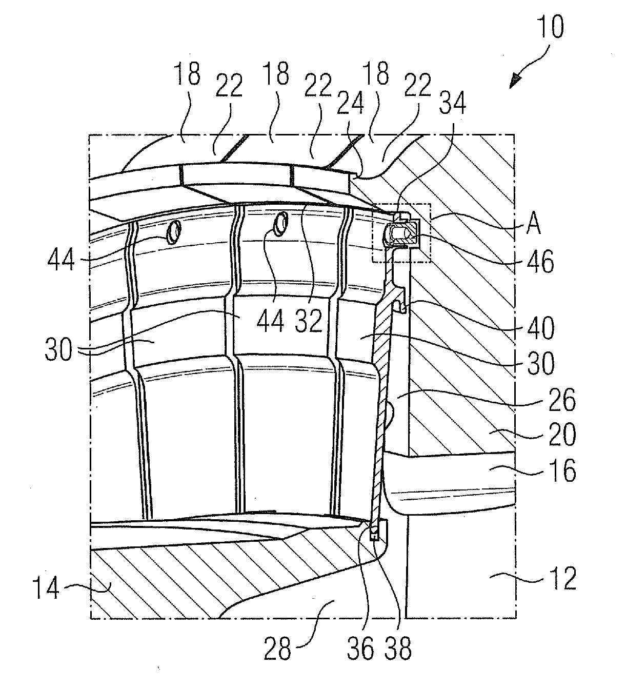
[0037]FIG. 1 shows in partially perspective, partially sectioned view a rotor section 10 for the rotor of a turbomachine, which is not additionally shown, which can be designed as a gas turbine. The rotor section essentially comprises on the one hand a first rotor disk 12 and a further rotor disk 14 which is adjacent thereto. The rotor disks 12, 14 are interconnected in a form-fitting manner by means of a Hirth toothing, which is not shown, for the transmission of torque, and are clamped to each other via a tension bolt, which is not additionally shown. The rotor section 10, alternatively to the depicted representation, could also be formed from a single piece in the form of a monoblock or from a singe rotor disk. On the outer periphery of the rotor section 10, provision is made for a plurality of rotor blade retaining grooves 16 which in each case extend at least partially in the axial direction of the rotor and of which only one is shown in section. The rotor blade retaining groov...


PUM


Abstract

A rotor section for a rotor of a gas turbine is provided. The rotor section includes a rotor disk with rotor blades inserted in retaining grooves thereupon, the rotor blades being secured against displacement along the retaining grooves by means of a sealing element which is arranged on the end face. In order to disclose a reliable construction which can be designed in a straightforward and simple manner for the circumferential fixing of the sealing element, each sealing element is secured by means of a blocking element in each case which in this case engages in a hole which is arranged in the rotor blade root on the end face.

Description

CROSS REFERENCE TO RELATED APPLICATIONS[0001]This application is a continuation of application Ser. No. 13 / 201,877 filed on Aug. 16, 2011 which is the US National Stage of International Application No. PCT / EP2010 / 050934, filed Jan. 27, 2010 and claims the benefit thereof. The International Application claims the benefits of European Patent Office application No. 09002223.7 EP filed Feb. 17, 2009. All of the applications are incorporated by reference herein in their entirety.FIELD OF INVENTION[0002]The invention refers to a rotor section according to the preamble of the claims. The invention furthermore refers to a rotor blade according to the preamble of the claims.BACKGROUND OF INVENTION[0003]An axial rotor section according to generic type for a turbine or a turbine rotor is known from laid open specification DE 1 963 364, for example. The rotor section, which comprises a rotor disk, has on its outer periphery a plurality of axially extending retaining grooves for rotor blades of ...

Claims


Application Information

Patent Timeline
Patent Type & Authority Applications(United States)
IPC IPC(8): F01D5/18
CPCF01D5/081F01D5/3015Y02T50/676F01D5/326Y02T50/673F01D5/323Y02T50/60F01D5/08F01D5/30F16B21/02F16B21/04
Inventor AHAUS, GUIDOBUSCHMANN, AXELDUNGS, SASCHAHOELL, HARALDKOLK, KARSTENMILAZAR, MIRKOSCHRODER, PETERVEITSMAN, VYACHESLAV
Owner SIEMENS ENERGY GLOBAL GMBH & CO KG
Why Eureka
Try Eureka