Apparatus for converting a pistol into a weapon simulator

a technology for converting a working which is applied in the field of apparatus for converting a semiautomatic pistol into a weapon simulator, can solve the problems of limited realism, providing a realistic feel of a real weapon, and unable to meet the needs of real-life use, and achieves the effect of real-time firing sensation and easy removal for cleaning and maintenan

Active Publication Date: 2012-05-24
DVORAK VOJTECH
View PDF4 Cites 56 Cited by
  • Summary
  • Abstract
  • Description
  • Claims
  • Application Information

AI Technical Summary

Benefits of technology

[0015]The embodiments of the present invention are directed to an apparatus for converting a pistol into a weapon simulator (hereinafter referred to as “apparatus”) without the use of any special tools or requiring any alterations to the pistol so that the user is given a realistic firing sensation when they fire the weapon simulator and so that the weapon simulator can be converted back to a pistol that is capable of firing live ammunition. Most modern small arms are designed in such a way that major parts can be easily removed for cleaning and maintenance. Standard takedown procedures for cleaning and maintenance of a pistol are provided to the user by the pistol manufacturer and are also part of standard drill in armed forces. The removal and reinstallation of the barrel and recoil spring in a pistol or replacement of an empty magazine with a full magazine are skills entirely within the capabilities of an average shooter and are typically required for qualification in organized weapon training. The installation of the apparatus for converting a pistol into a weapon simulator has been simplified so that the installation of this novel apparatus to convert a pistol into a weapon simulator does not require more than these basic skills.

Problems solved by technology

Various attempts have been made to develop a realistic weapon simulator or to retrofit a working pistol into a simulator with limited success.
The combination of the features of this weapon prevents it from providing a realistic feel of a real weapon.
The recoiling element does not push back the slide and does not cycle the semiautomatic weapon's mechanism, thus only offering limited realism.
The simulated weapon described in U.S. Pat. No. 5,947,738 uses a special gas cartridge in the barrel of the weapon to activate a pressure switch within the barrel to activate a light emitter and does not provide a realistic feel of a real weapon.
The laser pistol described in U.S. Pat. No. 6,146,141 is a replica of a weapon that has an electronic trigger mechanism that does not offer the realistic feel of a real weapon.
The simulator also uses a switchover valve to activate the valve tappet that complicates the firing mechanism and the compressed gas vents through a slip fit around the striker that reduces the efficiency of the simulator.
The above-discussed attributes of the simulator provide for a very complicated and inefficient retrofit to a real weapon.
The recoil actuator of this simulator is built into the rear portion of the original pistol slide; therefore it requires the weapon slide to be milled out and is then no longer usable for live ammunition.
Also, a flexible hose connection between the magazine and barrel is problematic.
In this simulator, the magazine cannot be removed easily due to the magazine being tethered to the blow-hack assembly in the barrel of the gun and the design of the magazine does not provide room for a slide catch.
These changes prevent the simulator from providing a realistic feel of a real weapon.
This prevents the simulator from being able to provide the realistic feel of a real weapon.
This is a more complex design that requires both electricity and gas to produce recoil in the simulator.
The disadvantage of known simulators is that they are either built as non / firing gas operated replicas or they are converted real pistols where the conversion of the pistol to a simulator is difficult to implement, the conversion often requiring a specially trained technician to install the conversion components into the pistol and often making the conversion of the pistol to a simulator irreversible.

Method used


Image

  • Apparatus for converting a pistol into a weapon simulator
  • Apparatus for converting a pistol into a weapon simulator
  • Apparatus for converting a pistol into a weapon simulator

Examples


first embodiment

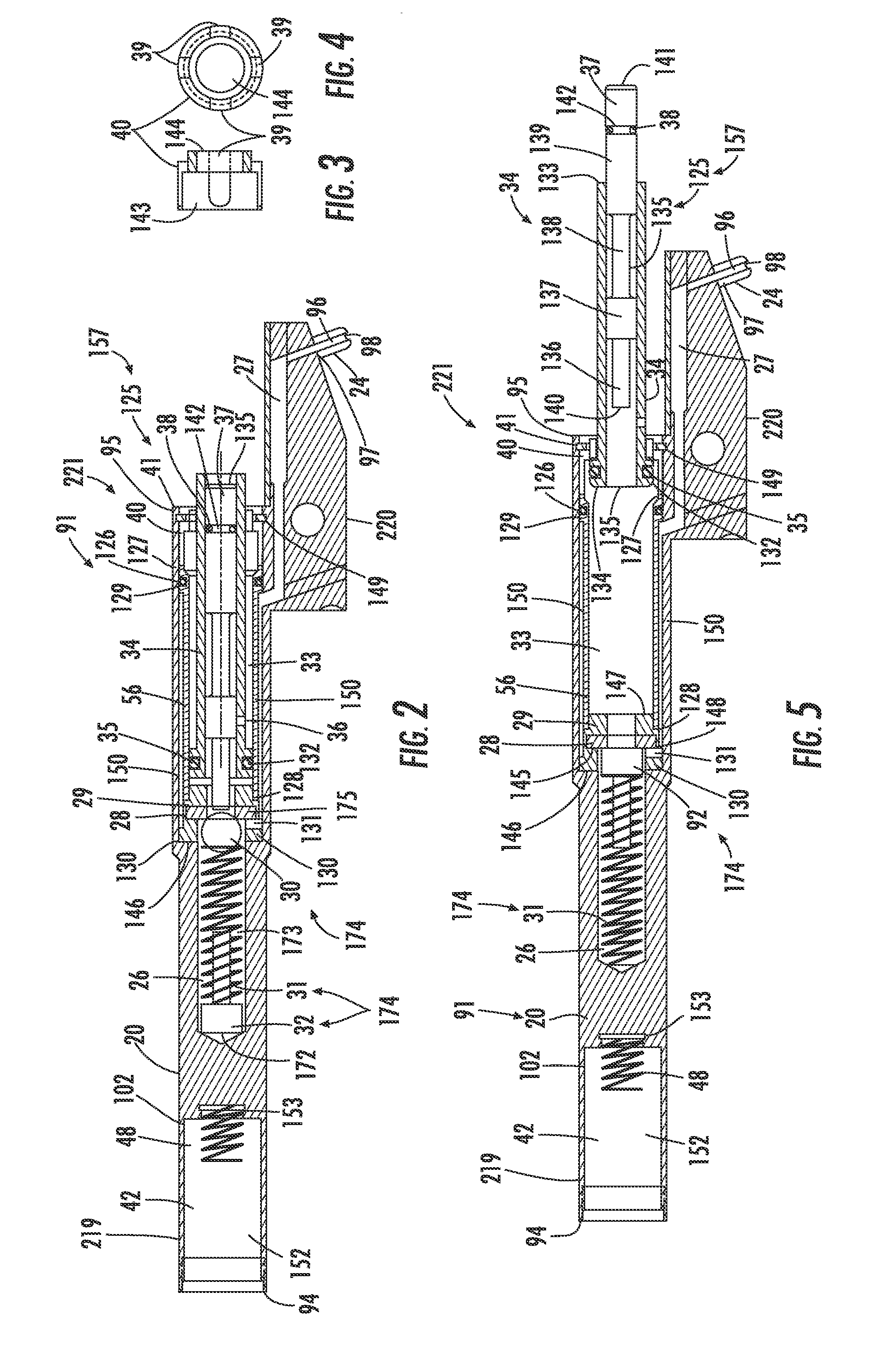
[0078]The extender mounting screw 23 having a first extender mounting screw end 164 and a second extender mounting screw end 165. The extender mounting screw 23 being made from metal or metal alloy material having a cylindrical shape with a plurality of threads being situated along a predetermined exterior length of the cylindrical shape, starting at the first extender mounting screw end 164, of a predetermined outside diameter that is substantially the same as the plurality of compressed gas valve cavity threads such that the plurality of threads on the first extender mounting screw end 164 are received in the plurality of compressed gas valve cavity threads to removably connect the barrel extender to the second barrel end 95, with a remaining exterior length of the extender mounting screw 23 of a predetermined outside diameter that is more than the predetermined outside diameter of the predetermined exterior length of the extender mounting screw 23 to form an L-shaped ledge along ...

third embodiment

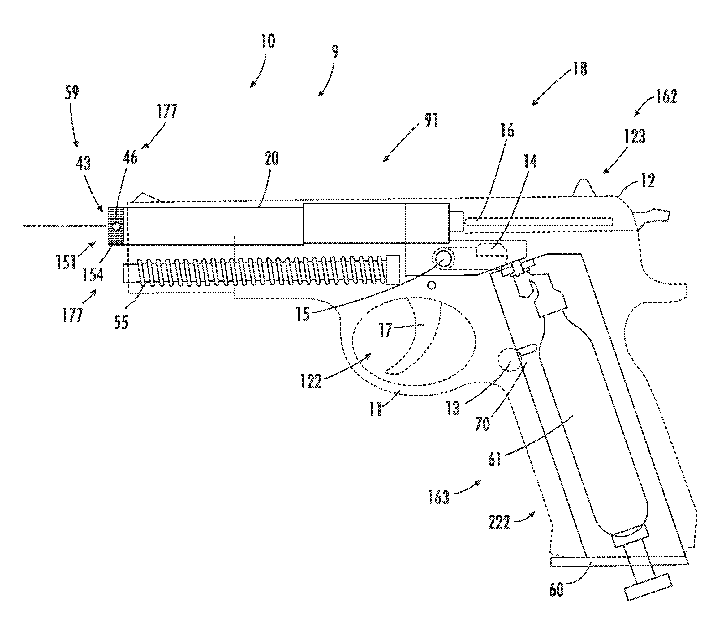
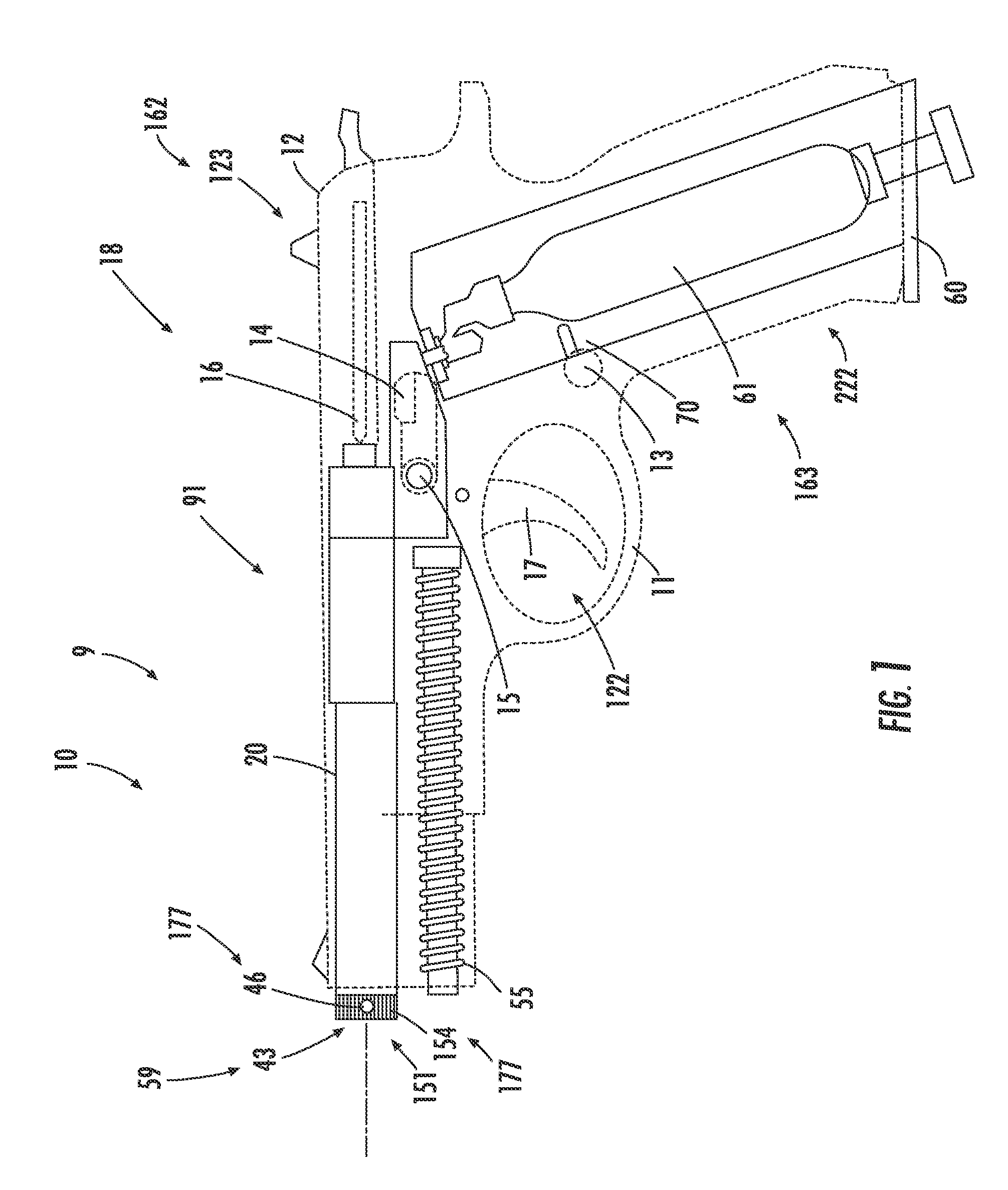
[0079]the barrel unit 91 is shown in FIG. 8, FIG. 9 and FIG. 10 where the barrel 20 is has a two-piece design to allow the barrel unit 91 to be received in a frame 11 that will not accommodate a one-piece barrel unit 91. In this embodiment of the present invention, the barrel unit 91 comprises a barrel 20, a compressed gas valve means 157, a compressed gas valve retaining means 221 and the firing mechanism actuated laser beam pulse emitting means 59. The compressed gas valve means 157 further comprises a compressed valve assembly 125. The compressed gas valve retaining means 221 further comprises a barrel extender seal 22, a bore cap 40, a bore cap retainer ring 41 and a barrel extender 21.

[0080]The barrel 20 having a laser module cavity 42, a first gas chamber 26, a compressed gas valve cavity 33, a barrel channel 27, and a first barrel extender seal chamber 100. The laser module cavity 42 is the same as previously described above. The compressed gas valve cavity 33 is situated at ...

fourth embodiment

[0082]the barrel unit 91 is shown in FIG. 11 and FIG. 12 where the barrel unit 91 has a two-piece design to allow the barrel unit 91 to be received in a frame 11 that will not accommodate a one-piece barrel unit 91 and where the striker 37 has a two section design. In this embodiment of the present invention, the barrel unit 91 comprises a barrel 20, a compressed gas valve means 157, a compressed gas valve retaining means 221 and the firing mechanism actuated laser beam pulse emitting means 59. The compressed gas valve means 157 further comprises a compressed valve assembly 125. The compressed gas valve retaining means 221 further comprises a barrel extender seal 22 and a barrel extender 21.

[0083]The barrel 20 having a laser module cavity 42, a first gas chamber 26, a compressed gas valve cavity 33, a barrel channel 27 and a first barrel extender seal chamber 100. The laser module cavity 42 is the same as previously described above. The compressed gas valve cavity 33 is situated at ...


PUM


Abstract

An apparatus for non-permanent conversion of a semiautomatic pistol into a compressed gas powered weapon simulator. The apparatus replaces the pistol's barrel, recoil spring and magazine with no modification of the pistol, which allows retaining the operational functions of the pistol's remaining components. Compressed gas, from the simulation magazine unit, is used in the compressed gas valve means, in the barrel unit, to operate the slide mechanism, to compress the simulation recoil spring, and to emit a laser pulse beam on a target when activated by the firing mechanism; and battery power, from the simulation magazine unit, is used to count the number of shots, lock the slide after a predetermined number of shots and transmit information from the weapon simulator to a remote data system. The compressed simulation recoil spring returns the slide mechanism back to its original position, unless locked open by the apparatus.

Description

BACKGROUND OF THE INVENTION[0001]1. Field of the Invention[0002]The present invention relates to a novel apparatus for converting a semiautomatic pistol (hereinafter referred to as a “pistol”) into a simulator so that the pistol converted into a simulator (hereinafter referred to as a “weapon simulator”) can be used for training individuals in the use of a semiautomatic pistol without having to fire live ammunition. More particularly, the weapon simulator provides a realistic firing sensation by providing the proper feel and balance, the proper trigger response, the proper action of the slide mechanism, the proper recoil and the locking of the slide mechanism in the proper position after the specific number of shots have been fired by the weapon simulator, while marking the point of aim with a laser, which makes the weapon simulator a safe, realistic and cost effective training tool.[0003]2. Prior Art[0004]Various attempts have been made to develop a realistic weapon simulator or to...

Claims


Application Information

Patent Timeline
Patent Type & Authority Applications(United States)
IPC IPC(8): F41A33/00F41B11/62
CPCF41A33/02F41B11/62F41A33/06
Inventor DVORAK, VOJTECH
Owner DVORAK VOJTECH
Why Eureka
Try Eureka