Electrochemical sensor

a biosensor and electrode technology, applied in the field of electrochemical sensors, can solve the problems of affecting the electrical connection between the contact pad and the terminal, the preferable state of the electric connection might be lost, and the conventional technology is not structured to absorb the external force applied to the one end portion of the biosensor, etc., to achieve the effect of keeping the preferable state of the electric connection

Inactive Publication Date: 2012-05-24
ARKRAY INC
View PDF2 Cites 9 Cited by
  • Summary
  • Abstract
  • Description
  • Claims
  • Application Information

AI Technical Summary

Benefits of technology

[0043]According to the present invention, it is possible to provide the technology capable of properly absorbing the external force applied to the electrochemical sensor.
[0044]Further, according to the present invention, it is possible to provide the technology capable of keeping the preferable state of the electric connection even when the external force is applied to the electrochemical sensor.

Problems solved by technology

Thus, the conventional technology is not structured to absorb the external force applied to the one end portion of the biosensor through the movement of the biosensor.
Therefore, there is a possibility that tissues around the one end portion are damaged.
Moreover, if the external force is applied to the one end portion indwelled subcutaneously due to a muscular movement, force acting in a rotating direction occurs on the flat surface of the other end portion with the result that the one end portion deviates in position, whereby the contact between the contact pads and the terminals might lose its preferable state.

Method used


Image

  • Electrochemical sensor
  • Electrochemical sensor
  • Electrochemical sensor

Examples


first embodiment

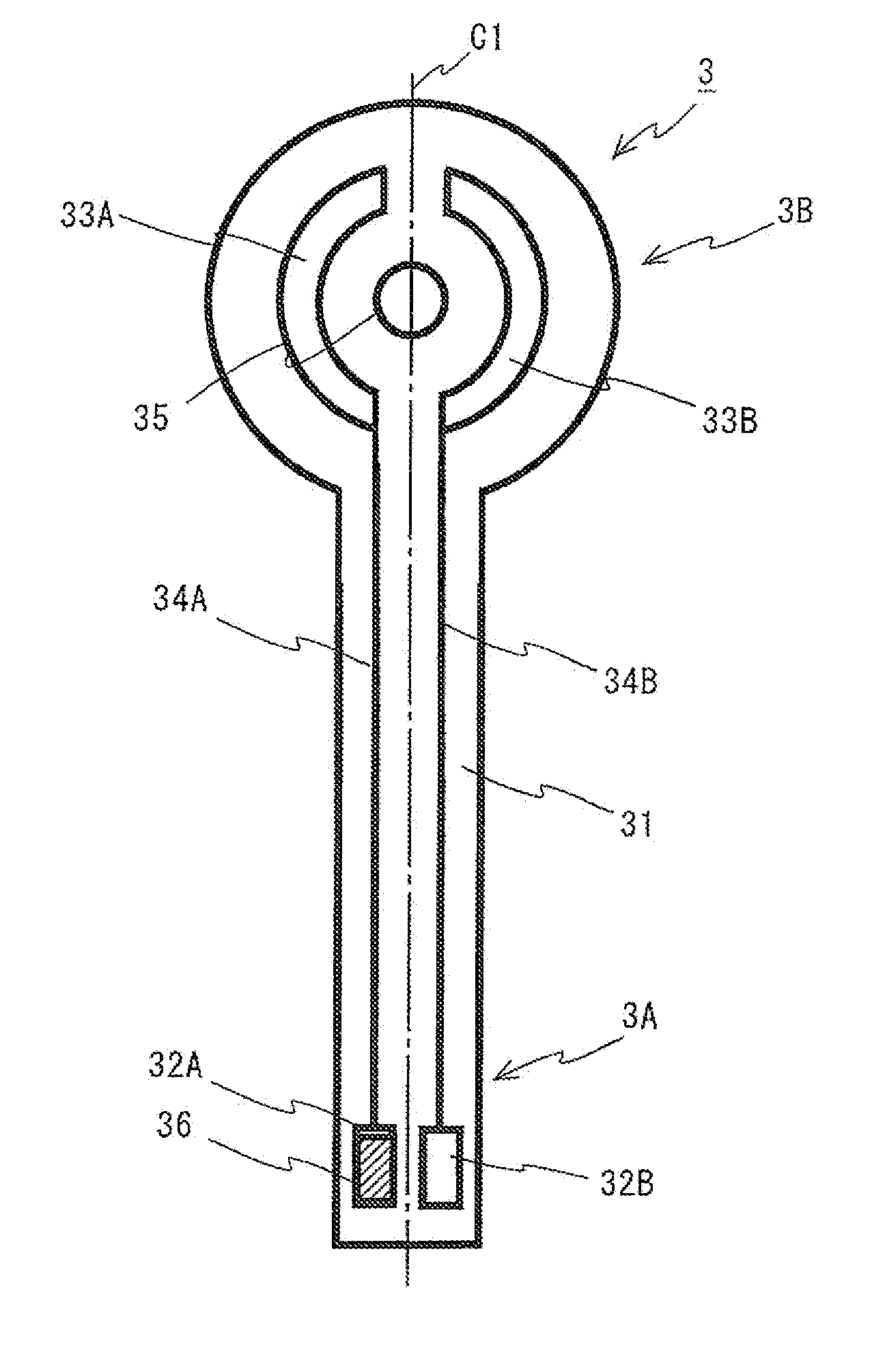
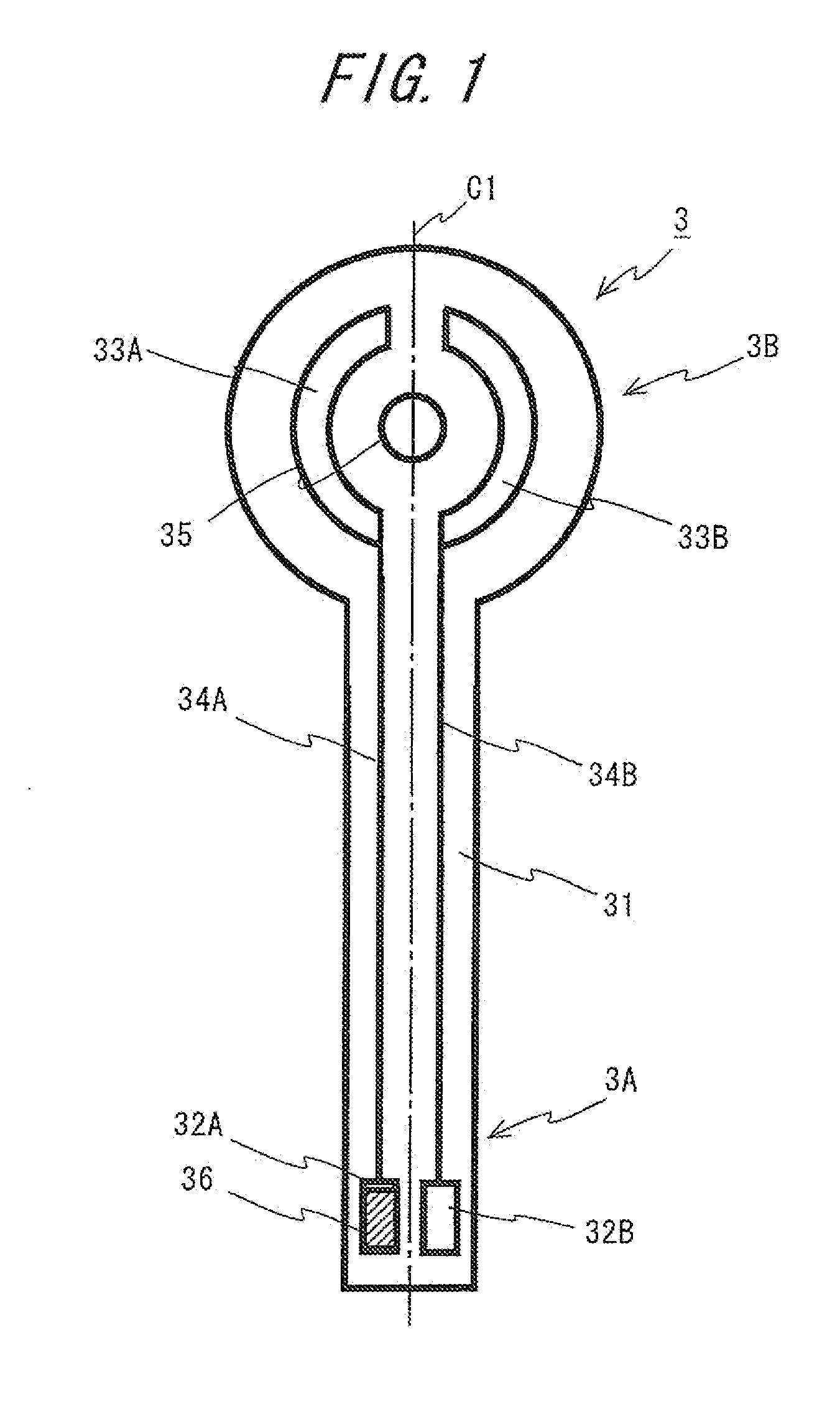
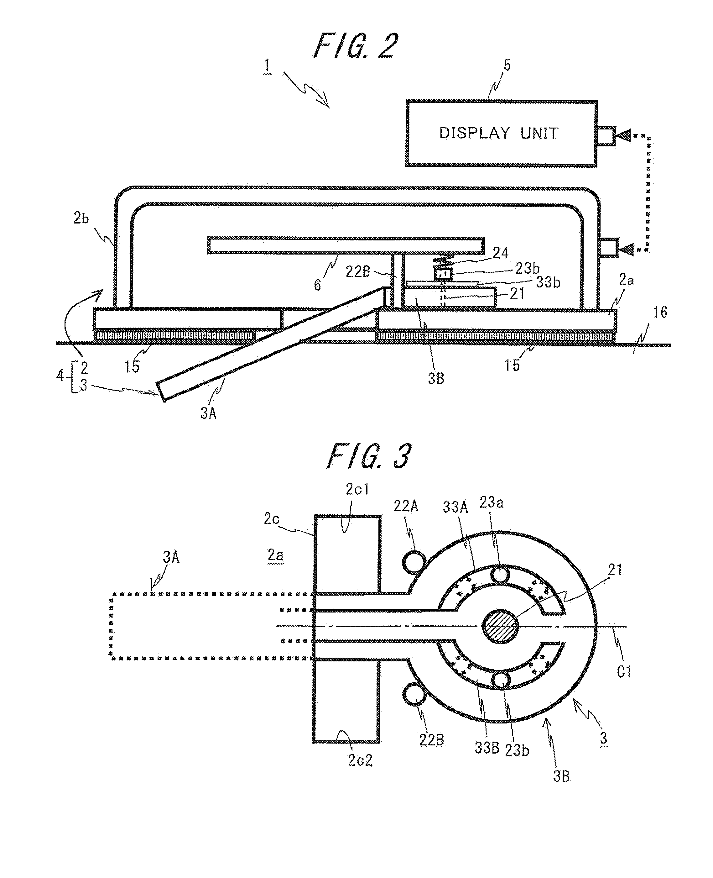
[0064]FIG. 1 is a view showing an example of a configuration of an electrochemical sensor according to a first embodiment of the present invention. FIG. 2 is a view illustrating an RT-CGM apparatus, to which the electrochemical sensor illustrated in FIG. 1 is applied, including a monitoring apparatus and a display unit. FIG. 3 schematically shows a state where the electrochemical sensor attached to the monitoring instrument is viewed in plane from above.

[0065]An RT-CGM apparatus (which will hereinafter be simply termed a monitoring apparatus) 1 shown in FIG. 2 is used for automatically continuously monitoring (measuring), as a physical quantity of a specified ground substance in a body fluid, a glucose concentration in an interstitial liquid of a human being and an animal (which are generically referred to as an examinee). The monitoring apparatus 1 includes a sensor unit 4 including a monitoring instrument 2 and an electrochemical sensor 3, and a display unit 5 serving as a data re...

second embodiment

[0117]Next, a second embodiment of the present invention will be discussed. The second embodiment embraces the points that are common to the first embodiment, and therefore the discussion will focus on different points in a way that omits the descriptions of the common points. Further, in the configurations of the glucose sensor and the monitoring instrument according to the second embodiment, the same components as those in the first embodiment are marked with the same numerals and symbols.

[0118]FIG. 7 is a view illustrating an example of a configuration of an electrochemical sensor (a glucose sensor 3c) according to the second embodiment. FIG. 8 schematically illustrates a state in which the glucose sensor 3c attached to the monitoring instrument is viewed in plane from above.

[0119]As illustrated in FIG. 7, the glucose sensor 3c according to the second embodiment is different from the glucose sensor 3 according to the first embodiment in terms of having a notched portion 71 as a s...

third embodiment

[0123]Next, a third embodiment of the present invention will be discussed. The third embodiment embraces the points that are common to the first embodiment, and therefore the discussion will focus on different points in a way that omits the descriptions of the common points. Further, in the configurations of the glucose sensor and the monitoring instrument according to the third embodiment, the same components as those in the first embodiment are marked with the same numerals and symbols.

[0124]FIG. 9 schematically illustrates a state in which the electrochemical sensor (a glucose sensor 3d) according to the third embodiment is attached to the monitoring instrument 2. FIG. 10 schematically, shows a state where the glucose sensor 3d attached to the monitoring instrument 2 is viewed in plane from above.

[0125]As depicted in FIGS. 9 and 10, the glucose sensor 3d according to the third embodiment has a recessed portion 81a and a recessed portion 81b in place of the through-hole 35 formed ...


PUM


Abstract

An electrochemical sensor includes a base plate including one end portion and another end portion, an electrode portion formed on the one end portion of the base plate, a connecting portion, formed on the another end portion of the base plate, for electrically connecting the electrode portion to a monitoring instrument, and an attaching portion formed on the another end portion, the attached portion being employed for attaching the another end portion to the monitoring instrument in a state where the one end portion is enabled to swing relatively to the monitoring instrument.

Description

[0001]This application claims the benefits of priority of the prior Japanese Patent Application No. 2010-115793 filed on May 19, 2010 and the Japanese Patent Application No. 2011-110947 filed on May 18, 2011, the entire contents of which are incorporated herein by reference.BACKGROUND OF THE INVENTION[0002]The present invention relates to an electrochemical sensor which is indwelled subcutaneously in human being and an animal and continuously measures (monitors) a physical quantity of components within a living organism.[0003]An RT-CGM (Real-Time Continuous Glucose Monitoring) apparatus performs a Continuous Glucose Monitoring (CGM) process for continuously measuring (monitoring) a concentration of glucose contained in a subcutaneous interstitial liquid by employing a biosensor, which has an electrode and an enzyme reacting on the glucose, indwelled subcutaneously.[0004]The RT-CGM device includes, as a basic configuration, a sensor unit and a data receiver which performs data commun...

Claims


Application Information

Patent Timeline
Patent Type & Authority Applications(United States)
IPC IPC(8): A61B5/1468
CPCA61B5/0002A61B5/14865A61B5/14532
Inventor KUSAKA, YASUHIDE
Owner ARKRAY INC
Why Eureka
Try Eureka