Manufacturing method of supporting structure for vehicle

Inactive Publication Date: 2007-05-17
NISSIN KOGYO CO LTD
View PDF5 Cites 2 Cited by
  • Summary
  • Abstract
  • Description
  • Claims
  • Application Information

AI Technical Summary

Benefits of technology

[0008] It is an object of the present invention to provide a manufacturing method of a supporting structure for vehicle characterized in that it is possible to inexpensively manufacture a supporting structure for absorbing and relaxing impact energy given to an object to be supported when the sup

Problems solved by technology

Concerning the method of forming such various supporting structures and portions which allow the supporting structures to be plastica

Method used


Image

  • Manufacturing method of supporting structure for vehicle
  • Manufacturing method of supporting structure for vehicle
  • Manufacturing method of supporting structure for vehicle

Examples


first embodiment

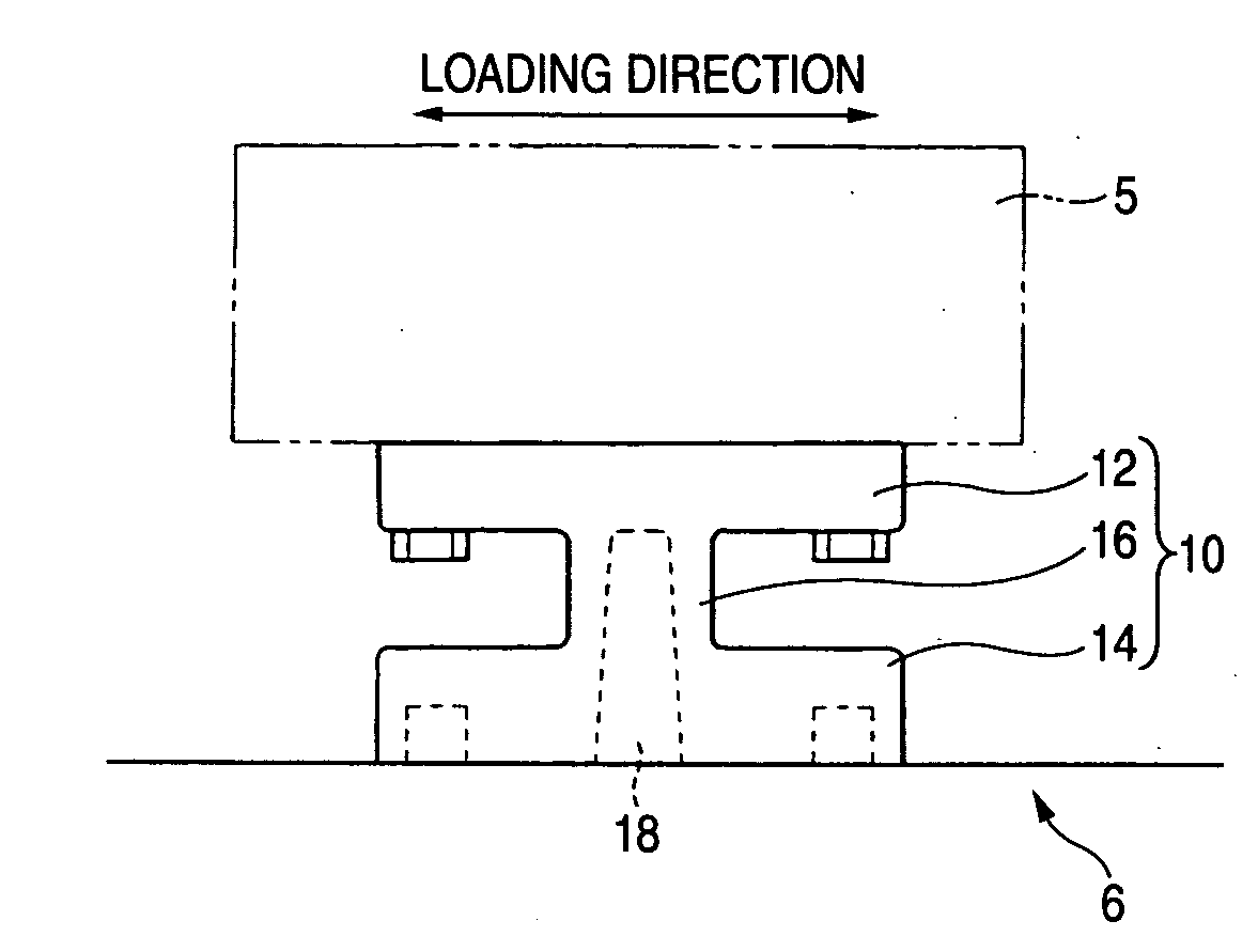
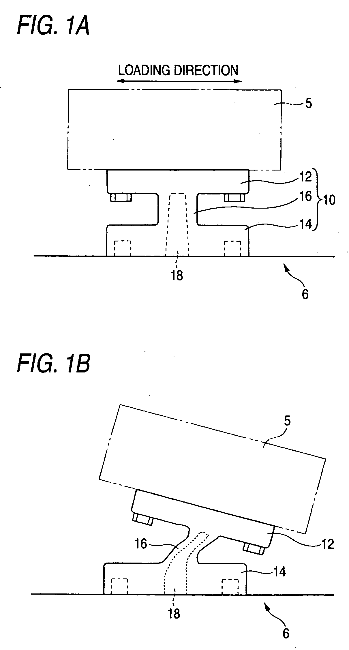
[0047]FIG. 1 is a view showing an example of a supporting structure for vehicle manufactured by the method of the present invention. In this view, an action of the supporting structure for vehicle is also shown. In the view, a supporting structure 10 includes: a first fixing portion 12 to which an object to be supported is fixed; a second fixing portion 14 fixed to a support portion 6 provided on the vehicle side; and a connecting portion 16 for integrally connecting the first fixing portion 12 with the second fixing portion 14. From a fixing face of the second fixing portion 14 to the connecting portion 16, a recess hole 18, which is open on the fixing face, is provided. Therefore, since a thin wall thickness portion is formed in the connecting portion 16, when a load of not less than a predetermined value is given to the object to be supported, the connecting portion 16 is plastically deformed and an impact can be absorbed.

[0048] In FIG. 1A, a loading direction of the object 5 to...

second embodiment

[0068]FIG. 4A is a view showing a casting mold used for the second embodiment of the manufacturing method of the supporting structure 10. In the same manner as that of the first embodiment, the casting mold 40 of the present embodiment is formed out of three casting mold including: a first casting mold 42 and a second casting mold 44 for forming the first fixing portion 12, the second fixing portion 14 and the connecting portion 16; and a third casting mold 46 for forming a fixing face and a recess hole 18 of the second fixing portion 14.

[0069] The present embodiment is characterized in that a groove 16c is formed on the outside of the side portion 16a perpendicular to the longitudinal direction of the first fixing portion 12 of the connecting portion 16 at the time of casting the supporting structure 10 with the casting mold.

[0070]FIG. 4A is a view showing a state in which a protrusion 42c, which is longitudinally arranged in the width direction of the side portion 16a, is provid...

third embodiment

[0075]FIG. 5A is a view showing a casting mold used for the third embodiment of the manufacturing method of the supporting structure 10. In the same manner as that of the first and the second embodiment, in the present embodiment, the supporting structure 10 is manufactured by means of casting with the first casting mold 42, the second casting mold 44 and the third casting mold 46 described before.

[0076] The present embodiment is characterized in that a recess portion 16d is formed on the outside 16b parallel with the longitudinal direction of the first fixing portion 12 of the connecting portion 16 at the time of casting the supporting structure 10 with the casting mold.

[0077]FIG. 5A is a view showing a state in which a protruding portion 42d, 44d for forming the recess portion 16d is formed on the forming face 42b, 44b which forms an outside of the side portion 16b of the connecting portion 16 formed in the first casting mold 42 and the second casting mold 44.

[0078]FIG. 5B is a...


PUM


Abstract

A manufacturing method of a supporting structure for vehicle has steps of preparing a casting mold having: a first and a second casting mold, which are matched to each other at casting, and has forming faces which form at least sides of first and second fixing portions and the connecting portion and a third casting mold having a forming face which forms a fixing face of the second fixing portion and a protruding body which forms a recess hole penetrating to an interior of the connecting portion from the fixing face of the second fixing portion; matching the third casting mold together with the first and the second casting mold so as to form a cavity for integrally forming the first fixing portion, the second fixing portion and the connecting portion in the casting mold; and pouring molten metal into the cavity so as to mold the supporting structure.

Description

BACKGROUND OF THE INVENTION [0001] 1. Field of the Invention [0002] The present invention relates to a manufacturing method of a supporting structure for vehicle. More particularly, the present invention relates to a manufacturing method of a supporting structure for vehicle characterized in that the supporting structure itself is plastically deformed when a load not less than a setting load is given to the supporting structure so that an impact force impressed upon the supporting structure can be relaxed. [0003] 2. Description of Related Art [0004] In a supporting structure for supporting and fixing an engine, transmission, differential gear and so forth, a mechanism is provided which absorbs and relaxes impact energy by the plastic deformation of the supporting structure itself when a load not less than a predetermined value is given by a collision to an object to be supported such as an engine attached to the supporting structure. [0005] For example, Japanese Patent Unexamined Pu...

Claims


Application Information

Patent Timeline
IPC IPC(8): B60K5/00
CPCB22C9/22F16F7/12F16M5/00F16M9/00Y10S180/902
Inventor KOBAYASHI, NAOKI
Owner NISSIN KOGYO CO LTD
Why Eureka
Try Eureka