Lubrication device of turbocharger of engine for vehicle

a technology of lubrication device and engine, which is applied in the direction of positive displacement liquid engine, liquid fuel engine, piston pump, etc., can solve the problems of vibration movement, assembly error of turbocharger, and difficulty in arranging components, etc., to increase the flexibility of engine layou

Inactive Publication Date: 2013-12-31
MAZDA MOTOR CORP
View PDF24 Cites 3 Cited by
  • Summary
  • Abstract
  • Description
  • Claims
  • Application Information

AI Technical Summary

Benefits of technology

[0010]An object of the present invention is to provide a lubrication device of a turbocharger of an engine for a vehicle which can increase the layout flexibility around the engine, absorb the vibration move of the first and second turbochargers relative to the engine, absorb the positional error between the first and second turbochargers, and the like.
[0012]According to the present invention, since the metal-made return passages of the first and second turbochargers are provided described above, the number of the return portion as the engine-side connection portion can be less than that of the return passages of the first and second turbochargers. Thereby, the return passages of the first and second turbochargers can be connected to the engine compactly by using a smaller layout space. Further, since only the one of the return passages is connected to the engine, the positional error of the other turbocharger relative to the engine does not influence this return passage, so that the assembly error of this return passage can be minimized Further, eve if the return passage of the second turbocharger is made from metal having a high heat resistance, the vibration move between the second turbocharger and the engine can be properly absorbed by the bellows-shaped vibration absorption portion. Moreover, since the flexible hose of the return passage of the first turbocharger can be shorter, the surface area exposed to the high temperature can be minimized Accordingly, the vibration move between the first turbocharger and the engine can be absorbed, preventing the heat damage of the flexible hose, so that the positional error between the first and second turbochargers can be absorbed properly.
[0013]According to an embodiment of the present invention, a turbine shaft of the first turbocharger and a turbine shaft of the second turbocharger are arranged substantially in parallel to each other, an exhaust-gas purification device is arranged on the side of one end of the turbine shaft, both the return passages of the first and second turbochargers are arranged on the side of the other end of the turbine shaft relative to the exhaust-gas purification device in an axial direction of the turbine shaft, and the return passage of the first turbocharger is arranged on the side of the other end of the turbine shaft relative to the return passage of the second turbocharger in the axial direction of the turbine shaft. Thereby, since the metal-made return passage of the second turbocharger is provided between the exhaust-gas purification device and the flexible hose and the distance between the exhaust-gas purification device and the flexible hose can be greater, the heat damage of the flexible hose by the exhaust-gas purification device can be restrained, so that the appropriate oil return of the first and second turbochargers can be secured.
[0014]According to another embodiment of the present invention, the exhaust-gas purification device is a diesel particulate filter. Thereby, even if the DPF (Diesel Particulate Filter) which tends to generate heat greatly is provided, the heat damage of the flexible hose can be restrained, so that the appropriate oil return of the first and second turbochargers can be secured.
[0015]According to another embodiment of the present invention, the first turbocharger is a turbocharger to operate at a low engine-speed, and the second turbocharger is a turbocharger which operates at a middle and high engine-speed. Thereby, the vibration move of the second turbocharger having the higher turbine speed can be absorbed by the long metal-made return passage of the second turbocharger which is equipped with the bellows-shaped vibration absorption portion, so that the reliability of the return passage of the second turbocharger can be secured.
[0016]According to another embodiment of the present invention, the lubricating oil supplied from the engine is supplied to an oil distributer from an oil gallery of a cylinder head, and then to the shaft bearing portions of the first and second turbochargers. Thereby, since the number of an oil take-out portion as the engine-side connection portion can be less than that of supply passages of the first and second turbochargers, the supply passages of the first and second turbochargers can be connected to the engine side wall compactly by using a smaller layout space, so that the layout flexibility around the engine can be increased.

Problems solved by technology

However, in the case of the two turbochargers being provided at the side wall of the engine as disclosed in the above-described first and second patent publications, the following problems may occur newly.
First, since the two turbochargers are provided at the side wall of the engine, each of the turbochargers requires the housing, oil passage for supply and return, cooling water passage for supply and return, and others, in addition to the passage for exhaust gas connecting the turbochargers, so that the layout of components around the engine may become difficult.
Therefore, there is a concern that arrangement of components, such as engine supplemental parts or engine-side connection portions of the oil return passages and the like, may become difficult.
Secondly, each turbocharger has its assembly error and vibration move relative to the engine's side wall.
Therefore, when the intake and exhaust passages of the turbo chargers are connected, the assembly error of one of the turbochargers relative to the engine-side connection portion may influence the assembly error of the oil return passage of the other turbocharger relative to the engine-side connection portion.
Accordingly, there is a concern that the assembly error of the two turbochargers may increase compared to the case of assembling a single turbocharger.
Further, in the case of the two turbochargers being assembled, the layout space becomes narrower and the heat-source number increases, so that the rubber-made oil return passage may also have its heat damage as well.

Method used


Image

  • Lubrication device of turbocharger of engine for vehicle
  • Lubrication device of turbocharger of engine for vehicle
  • Lubrication device of turbocharger of engine for vehicle

Examples


Embodiment Construction

[0036]Hereafter, a preferred embodiment of the present invention will be descried. In the embodiment the direction is described so that the “front” or “rear” means the vehicle front or the vehicle rear and the “right” or “left” means the right or left when viewed from the vehicle rear.

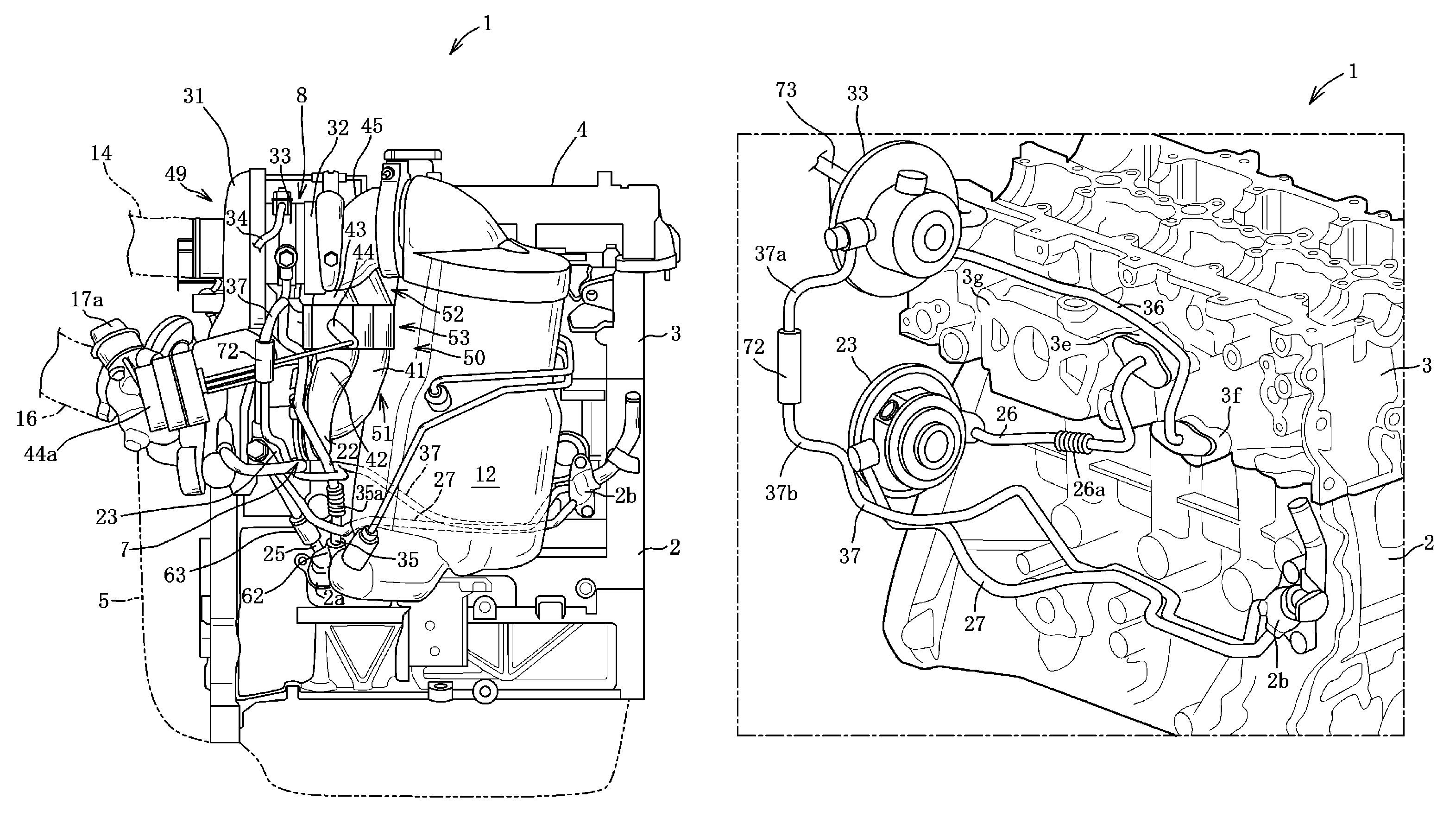
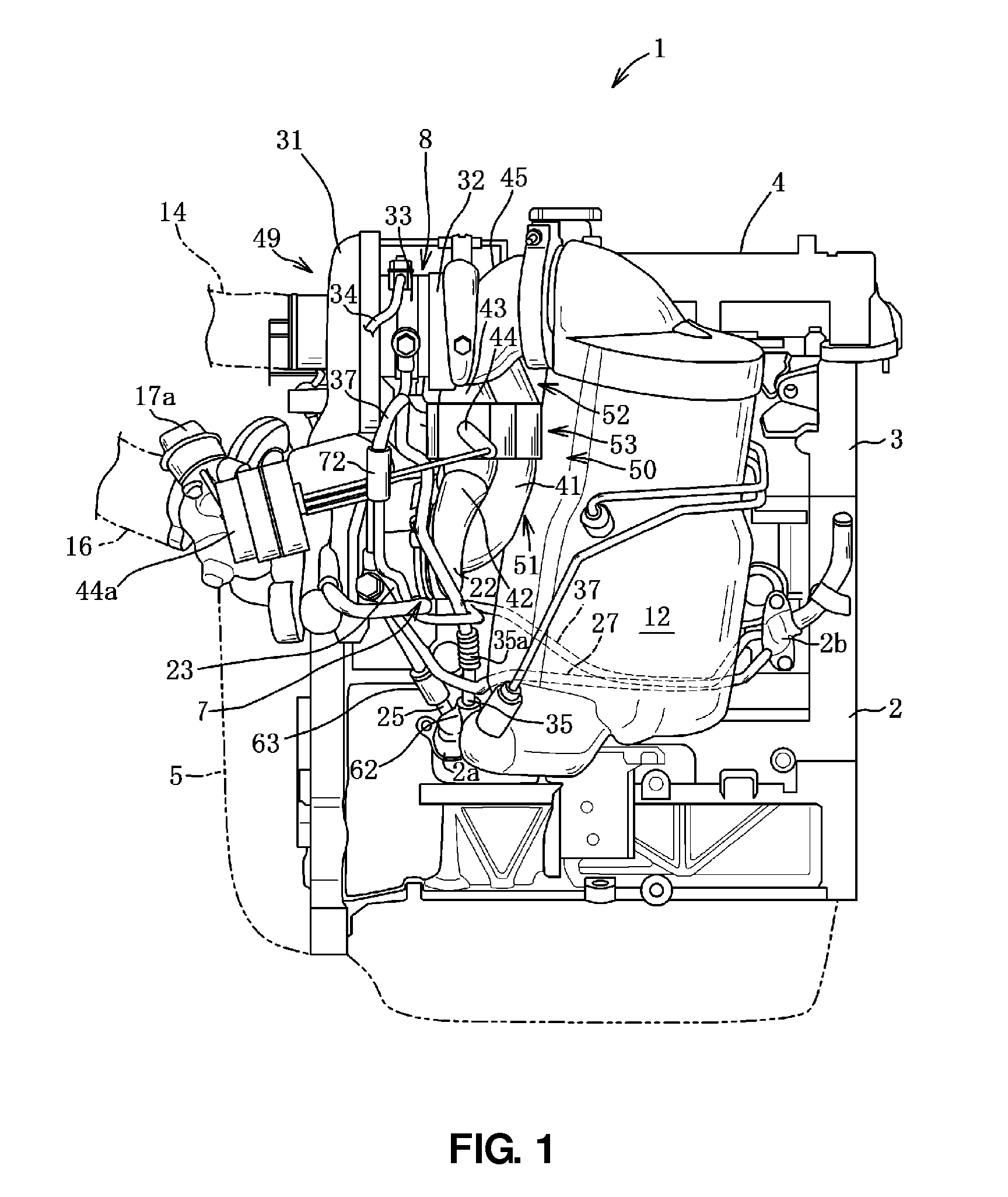
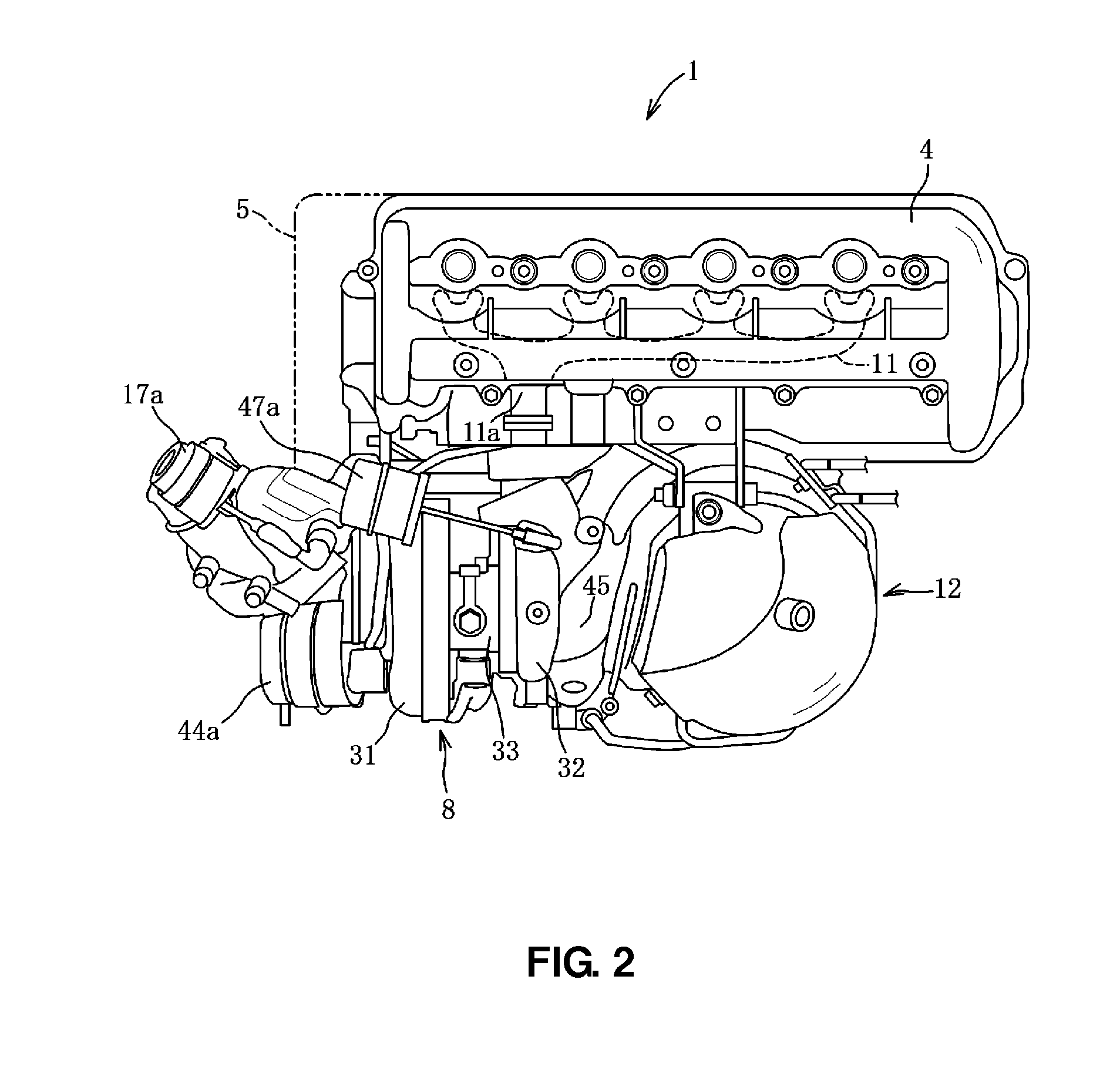
[0037]The present embodiment of the present invention will be described referring to FIGS. 1 through 18. As shown in FIGS. 1 through 3, an inline 4-cylinder diesel engine 1 comprises a cylinder block 2, a cylinder head 3 which is arranged above the cylinder block 2, a cylinder head cover 4 which covers over the cylinder head, a transmission unit 5 which is arranged at a left-side end portion of the cylinder block 2, and so on.

[0038]The engine 1 is disposed laterally so that the direction of its crankshaft (not illustrated) matches the direction of a vehicle axle, and intake ports 3a are positioned on the vehicle front side and exhaust ports 3b are positioned on the vehicle rear side. The engine 1 is co...


PUM


Abstract

A first turbocharger comprises a first center housing and a first return passage. A second turbocharger comprises a second center housing and a second return passage. The first return passage joins the second return passage at a junction. The length of the second return passage from the second center housing to the junction is longer than that of the first return passage from the first center housing to the junction. A bellows-shaped vibration absorption portion is provided at the second return passage. The first return passage comprises a first upstream return passage and a first downstream return passage, and the first upstream and downstream return passages are connected to each other via the flexible hose.

Description

BACKGROUND OF THE INVENTION[0001]The present invention relates to a lubrication device of a turbocharger of an engine for a vehicle, and in particular relates to the one in which a first turbocharger and a second turbocharger are provided at a one-side wall of the engine, the second turbocharger being located above the level of the first turbocharger.[0002]Conventionally, a turbo charging device to supercharge intake air by using the kinetic energy of exhaust gas exhausted from an engine is known. Further, a sequential type of turbo charging device, in which there are provided a small-sized turbocharger to supercharge the intake air mainly at a low engine-speed and low load and a large-sized turbocharger to supercharge the intake air mainly at a high engine-speed and high engine-load, and supercharging characteristics of the turbochargers are selectable in accordance with an engine's operation state, is known.[0003]In the turbo charging device disclosed in U.S. Pat. No. 6,782,849, t...

Claims


Application Information

Patent Timeline
Patent Type & Authority Patents(United States)
IPC IPC(8): F01D25/18F04B35/00F04B17/00F02B39/14F02B33/44F02B39/00
CPCF02B39/14F02B37/16F01N2340/06F02B37/004F01M2011/021F01D25/18F02B37/18Y02T10/144F05D2220/40F02B37/013F01N3/021Y02T10/12
Inventor NIWA, YASUSHINISHIMURA, KAZUAKINISHIZAKA, SATOSHIDEGUCHI, HIROAKI
Owner MAZDA MOTOR CORP
Why Eureka
Try Eureka