Cryo-rotary joint

a technology of rotating joints and sealing parts, which is applied in the direction of adjustable joints, mechanical equipment, engine components, etc., can solve the problems of affecting the function of sealing members, which are placed in contact with refrigerant, affecting the operation of sealing members, etc., and achieves the effect of high efficiency

Active Publication Date: 2012-05-31
TOKYO UNIV OF MANNE SCI & TECH
View PDF7 Cites 4 Cited by
  • Summary
  • Abstract
  • Description
  • Claims
  • Application Information

AI Technical Summary

Benefits of technology

[0050]The cryo-rotary joint according to the present invention includes the relatively rotating member configured to be cylindrical in shape and coaxial with the refrigerant tube and the rotating member and equipped with a fixed-side member fixed to the housing and a rotating-side member rotatably disposed inside the fixed-side member.
[0051]Since the fixed-side member of the cylindrical relatively rotating member is connected to the refrigerant tube via a refrigerant tube extension section and the rotating-side member of the relatively rotating member is connected to the rotating member via a rotating member extension section, the cylindrical relatively rotating member serves as a sealing portion, i.e., a portion where the rotating portion and fixed portion of the rotary joint move relative to each other.
[0052]In this way, being cylindrical in shape and installed coaxially with the refrigerant tube and the rotating member, the relatively rotating member according to the present invention can implement a cryo-rotary joint of smaller outside diameter than the conventional cryo-rotary joint in which part of the disk-shaped relatively rotating member in the radial direction is used for sealing.
[0053]Also, whereas the conventional cryo-rotary joint needs to have a large dimension in the length direction because the refrigerant supply channel and refrigerant return channel (inlet and outlet of the refrigerant tube) have to be installed serially in the length direction (direction...

Problems solved by technology

Also, functions of the sealing member, which is placed in contact with the refrigerant, is impaired by freezing.
Also, there will be leakage of the fluid.
Furthermore, frictional heat of ...

Method used


Image

  • Cryo-rotary joint
  • Cryo-rotary joint
  • Cryo-rotary joint

Examples


Embodiment Construction

[0078]Embodiments of the present invention will be described below.

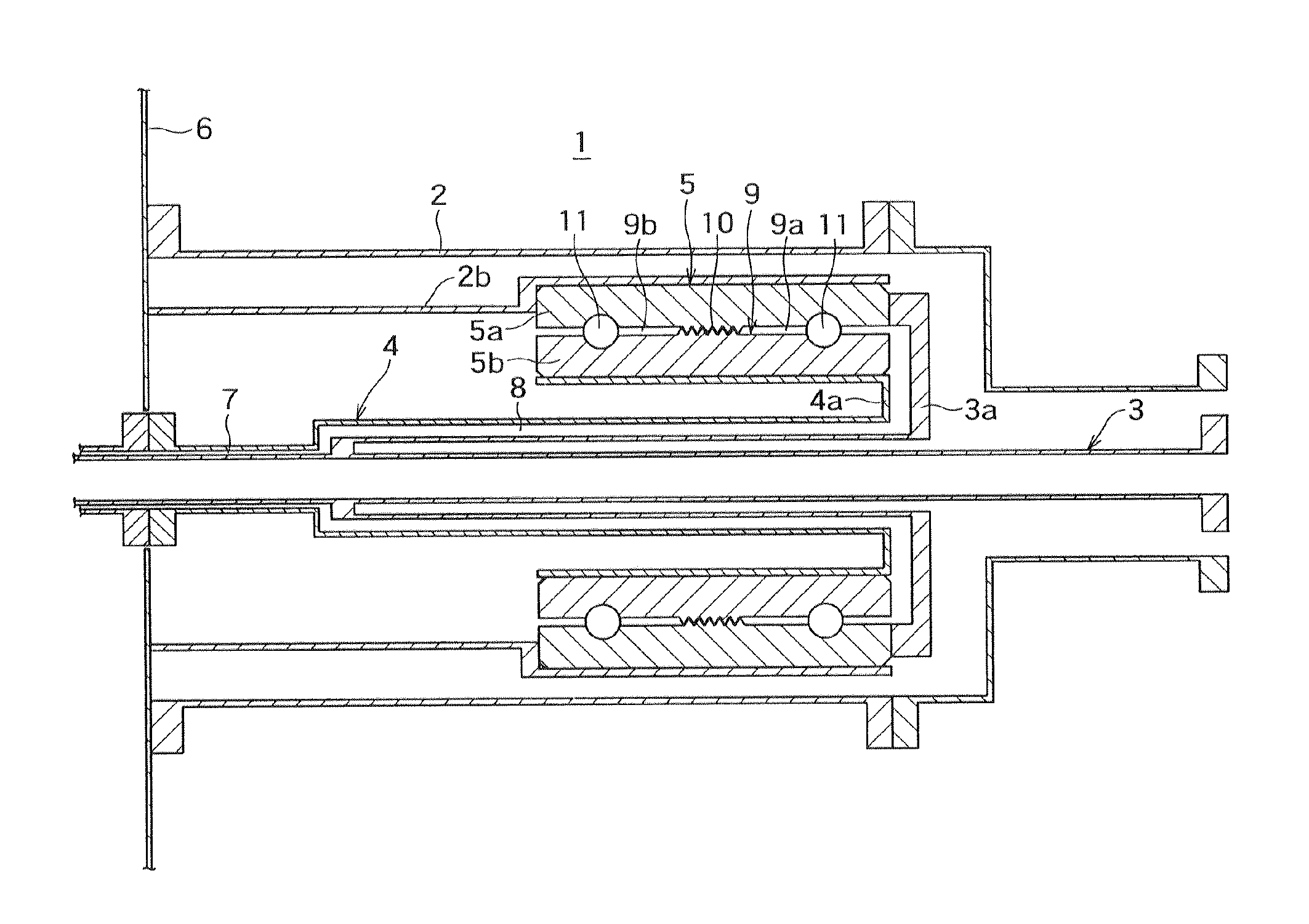
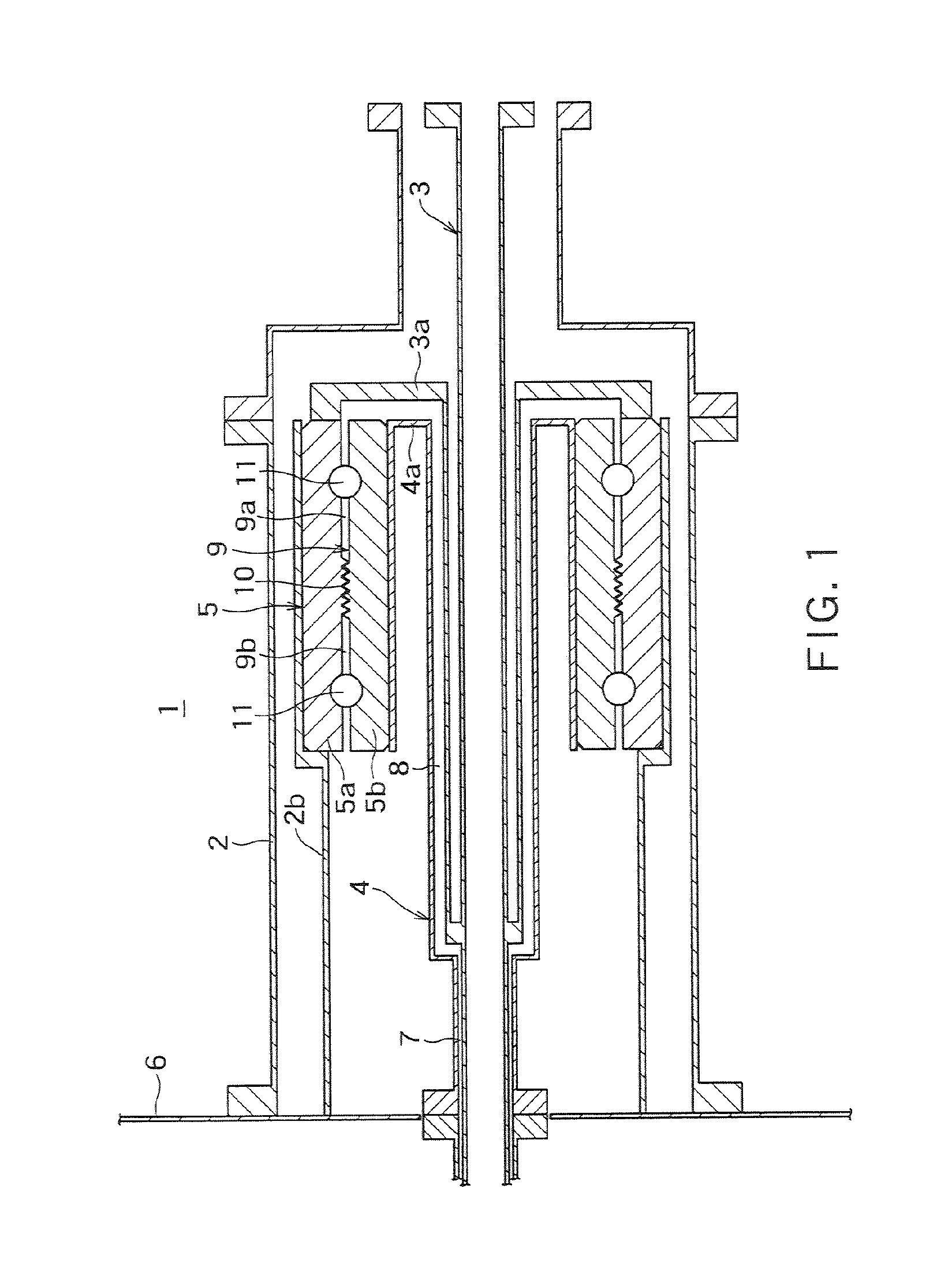
[0079]FIG. 1 shows a longitudinal sectional view of a cryo-rotary joint according to an embodiment of the present invention.

[0080]As shown in FIG. 1, the cryo-rotary joint 1 according to the present embodiment includes a housing 2, a non-rotating refrigerant tube 3, a rotating member 4 configured to be rotatable, and a relatively rotating member 5 cylindrical in shape.

[0081]The cryo-rotary joint 1 is mounted on an end wall 6 of a rotating machine (not shown). In FIG. 1, portions which rotate are shown shaded and portions which do not rotate are shown hatched indicating a cross section.

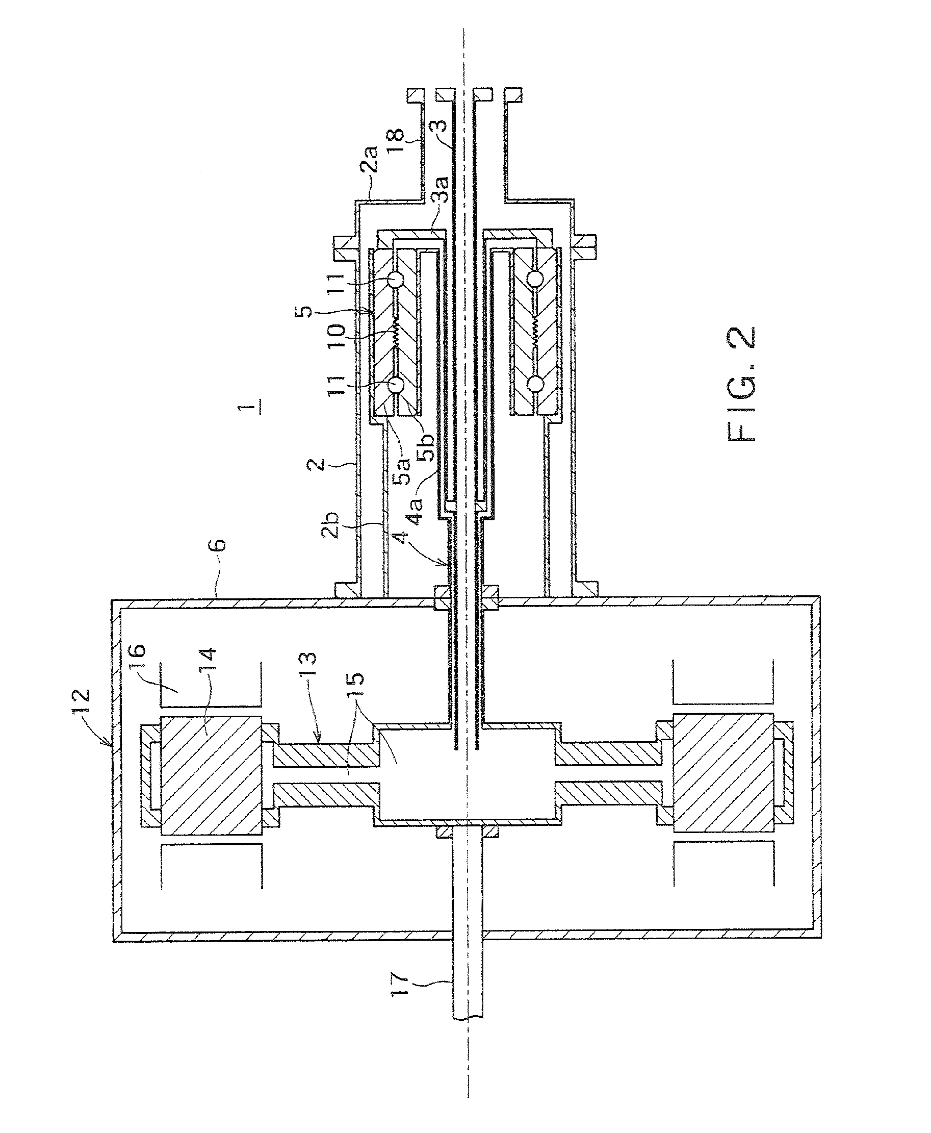
[0082]The refrigerant tube 3 is installed within the housing 2, connected at one end to an external refrigerant source (not shown), communicated at the other end with a target part (not shown) in the rotating machine, and adapted to allow a refrigerant to pass inside.

[0083]Preferably, the refrigerant tube 3 is installed coaxially with a...


PUM


Abstract

Problem to be Solved
To provide a small, lightweight, cryo-rotary joint.
Solution
A joint includes a housing 2, a refrigerant tube 3 connected to a refrigerant source and communicated with a target part in a rotating machine, a rotating member 4 loosely fitted inside with the refrigerant tube and fixed to a rotary part of the rotating machine, and a relatively rotating member 5 having a fixed-side member 5a and rotating-side member 5b, wherein the fixed-side member is connected to the refrigerant tube via a refrigerant tube extension section 3a, the rotating-side member is connected to the rotating member via a rotating member extension section 4a, a refrigerant zone is formed by spaces 7 and 8 defined by the refrigerant tube, rotating member, and refrigerant tube and rotating member extension sections, a sealing member 10 is installed between the fixed-side and rotating-side members, and a vacuum chamber and pressure chamber are defined within the housing.

Description

TECHNICAL FIELD[0001]The present invention relates to a cryo-rotary joint.[0002]More particularly, the present invention relates to a cryo-rotary joint which lends itself to extreme downsizing by using a structure in which a cylindrical relatively rotating member is used for a sealing portion between a rotary part and stationary part of the rotary joint and a refrigerant tube is passed internally through the relatively rotating member.[0003]Also, the present invention relates to a cryo-rotary joint which can prevent freezing of a sealing member by placing a sealing portion between a rotary part and stationary part of the rotary joint at a location thermally distant from a target part in a rotating machine, prevent loss of a refrigerant due to frictional heat of the sealing portion, and prevent conduction heat via tubes from outside.BACKGROUND ART[0004]Generally, a rotary joint refers to a mechanism which can join a fixed portion and rotating portion of a machine and circulate a flui...

Claims


Application Information

Patent Timeline
IPC IPC(8): F16L27/08F16J15/43F16L19/08
CPCF16C33/765F16L59/141F16L59/185F16C2361/00H02K55/04Y02E40/625F16L27/08Y02E40/60
Inventor IZUMI, MITSURUMIKI, MOTOHIROKITANO, MASAHIRO
Owner TOKYO UNIV OF MANNE SCI & TECH
Why Eureka
Try Eureka