Turning device for wind turbine rotor and wind turbine generator including the same

a technology of wind turbine generator and turning device, which is applied in the direction of electric generator control, machines/engines, mechanical equipment, etc., can solve the problems of increasing the manufacturing cost of wind turbine generators, and expensive equipment in the turning device, so as to achieve simple and inexpensive configuration, no damage, and easy to turn.

Inactive Publication Date: 2012-05-31
MITSUBISHI HEAVY IND LTD
View PDF2 Cites 25 Cited by
  • Summary
  • Abstract
  • Description
  • Claims
  • Application Information

AI Technical Summary

Benefits of technology

[0012]The present invention has been conceived to solve the problems described above, and an object thereof is to provide a turning device for a wind turbine rotor and a wind turbine generator including the same in which, through a simple and inexpensive configuration, the wind turbine rotor can be easily turned to an arbitrary position, and damage is not caused even when there is a large torque fluctuation caused by the wind turbine rotor receiving a gust of wind.

Problems solved by technology

Hence, the turning device is expensive equipment although its frequency of use is low with respect to the operating time of the wind turbine generator, and this has been a cause of the increase in the manufacturing costs of wind turbine generators.
With the turning device according to US Patent Application, Publication No. 2009 / 0278359, since the driving force of the electric motor is transmitted to the rotary shaft of the gearbox via the relatively expensive gear mechanism, this has also increased the manufacturing costs.
Furthermore, if the structure is such that the motive power of the electric motor is transmitted to the wind turbine rotor by the gear mechanism, in the event of a large torque fluctuation caused by the wind turbine rotor due to a gust of wind generated while turning the wind turbine rotor when the wind speed is low, the torque fluctuation will be directly transmitted to the electric motor, and thus, there is a concern that driving-power transmitting parts, such as the electric motor, the gear mechanism, etc., may be damaged.

Method used


Image

  • Turning device for wind turbine rotor and wind turbine generator including the same
  • Turning device for wind turbine rotor and wind turbine generator including the same
  • Turning device for wind turbine rotor and wind turbine generator including the same

Examples


Embodiment Construction

[0041]An embodiment of the present invention will be described below with reference to FIGS. 1 to 8.

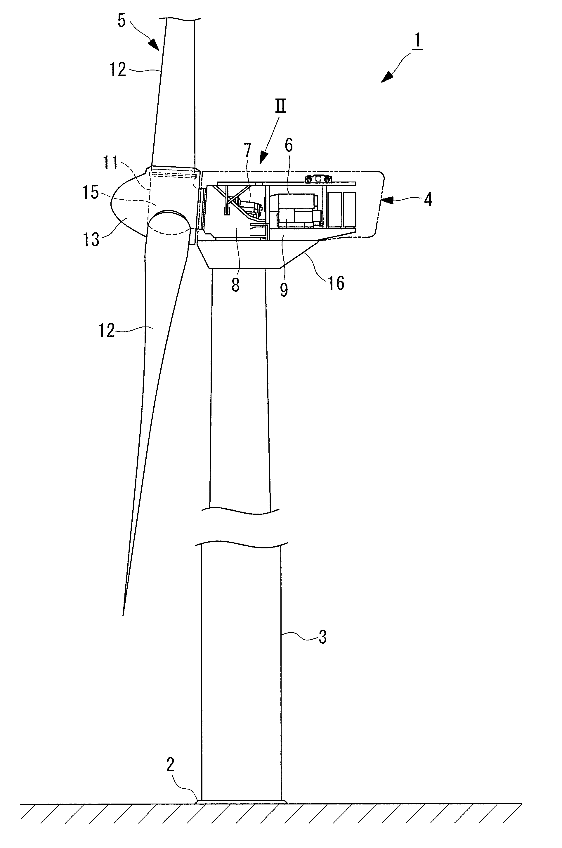
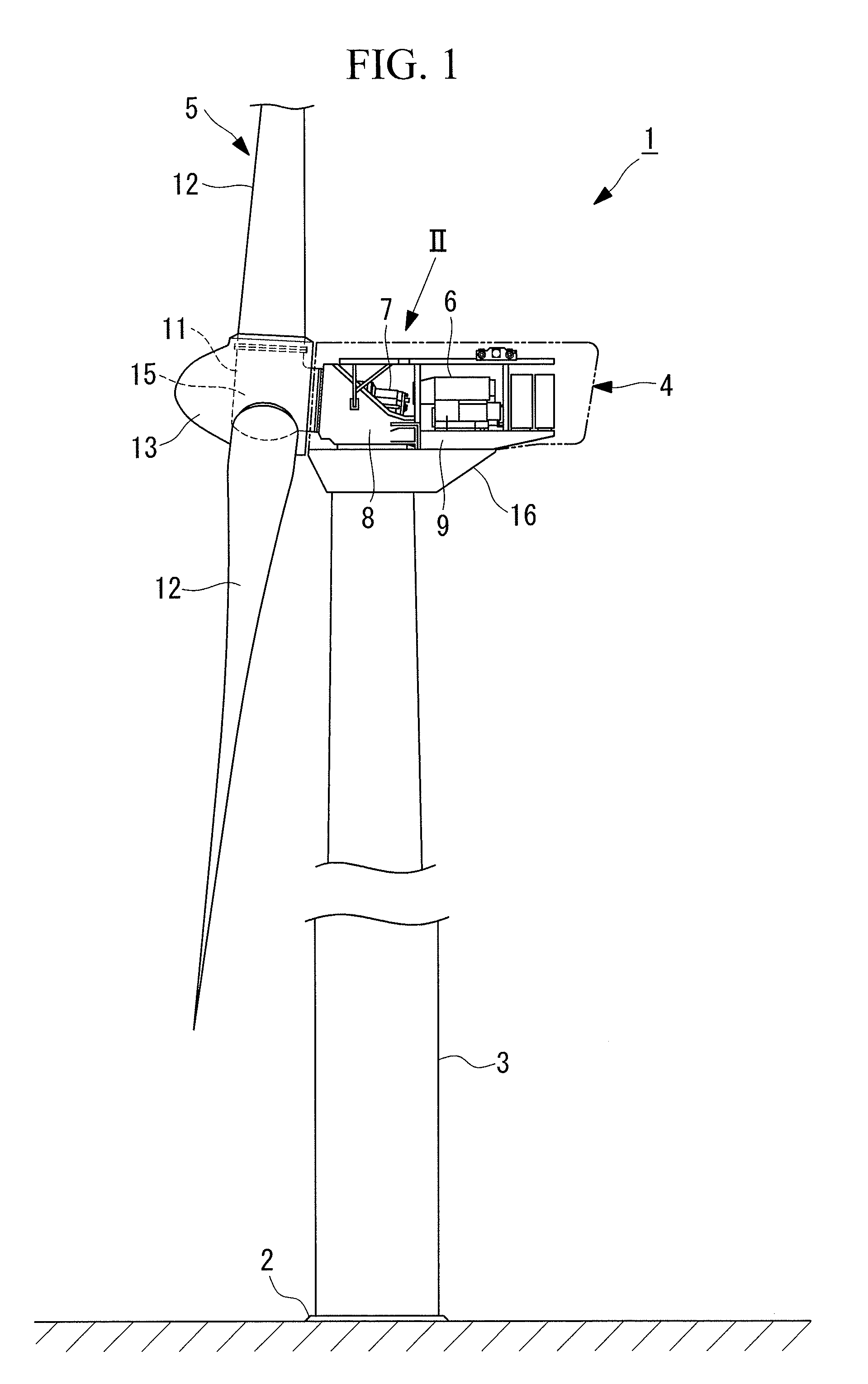
[0042]FIG. 1 is a side view of an example of a wind turbine generator to which a turning device according to an embodiment of the present invention can be applied. The wind turbine generator 1 includes a tower 3 vertically disposed on the upper surface of a reinforced concrete foundation 2, which is, for example, embedded in the ground; a nacelle 4 disposed at the upper end of the tower 3; a wind turbine rotor 5 disposed on the nacelle 4; and a generator 6 and gearbox 7, which are accommodated inside the nacelle 4 and generate electric power by means of the rotation of the wind turbine rotor 5.

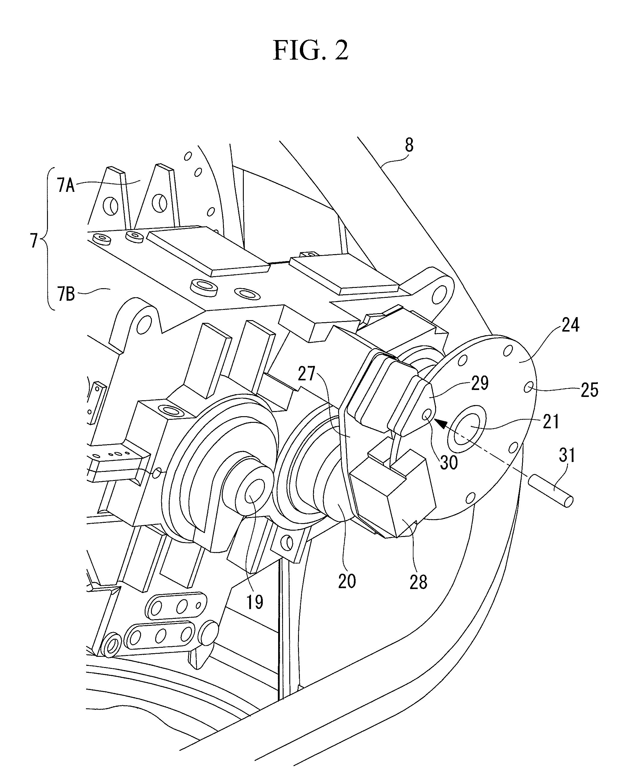
[0043]The gearbox 7 is accommodated inside a highly rigid steel nacelle bed plate 8, together with a main bearing (not shown), which axially supports the main shaft of the wind turbine rotor 5; and the nacelle bed plate 8 is axially supported at the upper end of the tower 3 in such a manner that...


PUM


Abstract

A turning device includes a brake disc, functioning as a driven-side friction pulley, which is disposed on an output shaft of a gearbox and rotates together with the output shaft; a motor-side friction pulley, which can move between an engagement position, where the motor-side friction pulley frictionally engages with an outer circumferential surface of the brake disc, and a free position, where the motor-side friction pulley is a certain distance away from the outer circumferential surface of the brake disc; a pulley pressing mechanism, which moves the motor-side friction pulley from the free position to the engagement position by manual power of an operator to frictionally engage the motor-side friction pulley with the outer circumferential surface of the brake disc; and pulley driving means (electric motor, etc.) for rotationally driving the motor-side friction pulley.

Description

CROSS REFERENCE TO RELATED APPLICATIONS[0001]This application is a continuation application of PCT / JP2011 / 073336 filed on Oct. 11, 2011, the contents of which is hereby incorporated by its reference.BACKGROUND OF THE INVENTION[0002]1. Field of the Invention[0003]The present invention relates to a turning device for a wind turbine rotor that rotates a wind turbine rotor to a desired position when wind speed is low and relates to a wind turbine generator including the same.[0004]2. Description of Related Art[0005]A typical propeller-type wind turbine generator includes a wind turbine rotor having a plurality of wind-turbine blades attached to a rotor head, serving as a center of rotation. The wind turbine rotor is axially supported on a nacelle, which is supported at the top of a tower in a yawable manner; and a gearbox and a generator are disposed inside the nacelle. When the wind turbine rotor rotates by receiving wind, the rotation is sped-up at the gearbox and is transmitted to th...

Claims


Application Information

Patent Timeline
Patent Type & Authority Applications(United States)
IPC IPC(8): F03D9/00H02K7/10
CPCF03D1/003F03D7/0268Y02E10/725Y02E10/723F05B2260/902F03D80/50F05B2260/31Y02E10/72F03D1/00F03D7/04
Inventor NUMAJIRI, TOMOHIRO
Owner MITSUBISHI HEAVY IND LTD
Why Eureka
Try Eureka