Unlock instant, AI-driven research and patent intelligence for your innovation.

Reference Voltage Buffer and Method Thereof

a voltage buffer and reference voltage technology, applied in the field of reference voltage buffers, can solve the problem that high-speed circuits typically consume more power

Active Publication Date: 2012-05-31
REALTEK SEMICON CORP
View PDF4 Cites 6 Cited by
  • Summary
  • Abstract
  • Description
  • Claims
  • Application Information

AI Technical Summary

Benefits of technology

[0009]In an embodiment, an apparatus comprises: an OTA (operational trans-conductance amplifier) with a positive input terminal coupled to a reference voltage, a negative input terminal coupled to a feedback node, and an output terminal shunt to a ground node via a shunt capacitor; a resistor coupling the output terminal of the OTA to the feedback node; and a load circuit coupled to the feedback node via a switch controlled by a logical signal, wherein: an impedance of the shunt capacitor is substantially smal...

Problems solved by technology

As is known, higher speed circuits typically consume more power.

Method used


Image

  • Reference Voltage Buffer and Method Thereof
  • Reference Voltage Buffer and Method Thereof
  • Reference Voltage Buffer and Method Thereof

Examples


Embodiment Construction

[0014]The present invention relates to a reference voltage buffer, in particular to reference voltage buffer for switch-capacitor circuits. While the specifications described several example embodiments of the invention considered best modes of practicing the invention, it should be understood that the invention can be implemented in many ways and is not limited to the particular examples described below or to the particular manner in which any features of such examples are implemented. In other instances, well-known details are not shown or described to avoid obscuring aspects of the invention.

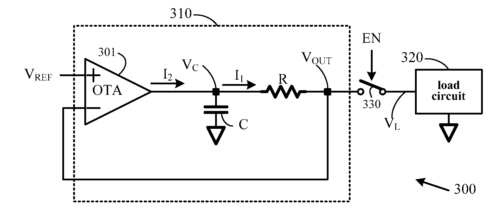
[0015]An exemplary circuit 300, constructed in accordance with an embodiment of the present invention, is depicted in FIG. 3. Circuit 300 comprises: a reference voltage buffer 310 for receiving a reference voltage VREF and outputting an output voltage VOUT, a switch 330 controlled by a logical signal EN, and a load circuit 320 coupled to the output voltage via the switch 330. The switch 330 i...


PUM


Abstract

An apparatus comprises: an OTA (operational trans-conductance amplifier) with a positive input terminal coupled to a reference voltage, a negative input terminal coupled to a feedback node, and an output terminal shunt to a ground node via a shunt capacitor; a resistor coupling the output terminal of the OTA to the feedback node; and a load circuit coupled to the feedback node via a switch controlled by a logical signal, wherein: an impedance of the shunt capacitor is substantially smaller than an input impedance of the load circuit. In an embodiment, the load circuit is a switch capacitor circuit. A corresponding method using an OTA is also provided.

Description

BACKGROUND OF THE INVENTION[0001]1. Field of the Invention[0002]The present invention generally relates to reference voltage buffers, and more particularly to low-power, fast-reacting reference voltage buffers.[0003]2. Description of Related Art[0004]Reference voltage buffers are needed in numerous applications, e.g. pipeline ADC (analog-to-digital converter). The principles (e.g., structure and operation) of pipeline ADCs are well known in prior art and thus need not be described herein. For example, an illustrative pipelined ADC is described in U.S. Pat. No. 7,280,064. As described in U.S. Pat. No. 7,280,064, a pipeline ADC comprises a plurality of pipeline stages. A typical 1-bit pipeline stage 100 is depicted in FIG. 1. Pipeline stage 100 receives an input signal VI and generates an output signal VO and a 1-bit decision D. Pipeline stage 100 operates in accordance with a two-phase non-overlapping clock comprising a sampling phase Φ1 and a transfer phase Φ2. During the sampling p...

Claims


Application Information

Patent Timeline
IPC IPC(8): H03F3/45
CPCH03M1/44H03M1/002
Inventor LIN, CHIA-LIANG
Owner REALTEK SEMICON CORP
Features
  • R&D
  • Intellectual Property
  • Life Sciences
  • Materials
  • Tech Scout
  • Unparalleled Data Quality
  • Higher Quality Content
  • 60% Fewer Hallucinations
Learn More