Digital Requantization Process and Devices

a digital requantization and power supply technology, applied in the field of switchable mode power supply, can solve the problems of inability to work at such high resolution, low ripple frequency, and high probability of periodic production of error corrections, so as to improve the situation

Active Publication Date: 2012-05-31
TELEFON AB LM ERICSSON (PUBL)
View PDF3 Cites 2 Cited by
  • Summary
  • Abstract
  • Description
  • Claims
  • Application Information

AI Technical Summary

Benefits of technology

[0010]There is therefore a need to improve the situation.

Problems solved by technology

For technological and economic reasons, the use of a waveform generator 16 working at such high resolutions is not always practical.
The downside to this improvement is that the periodic production of error corrections is likely to introduce variations, called ripple, in the quantified signal.
This ripple is sufficiently low in frequency that the LC filter of the switched-mode power supply 1 is not able to apply effective averaging.
In addition, the ripples produced by the dithering processes of the prior art are likely to combine with other faults in the switched-mode power supply 1, particularly the ripple introduced by control faults of the set of power switches.
Ultimately, such dither ripple is detrimental to the overall precision of the signal that is output by the switched-mode power supply 1.

Method used


Image

  • Digital Requantization Process and Devices
  • Digital Requantization Process and Devices
  • Digital Requantization Process and Devices

Examples


Embodiment Construction

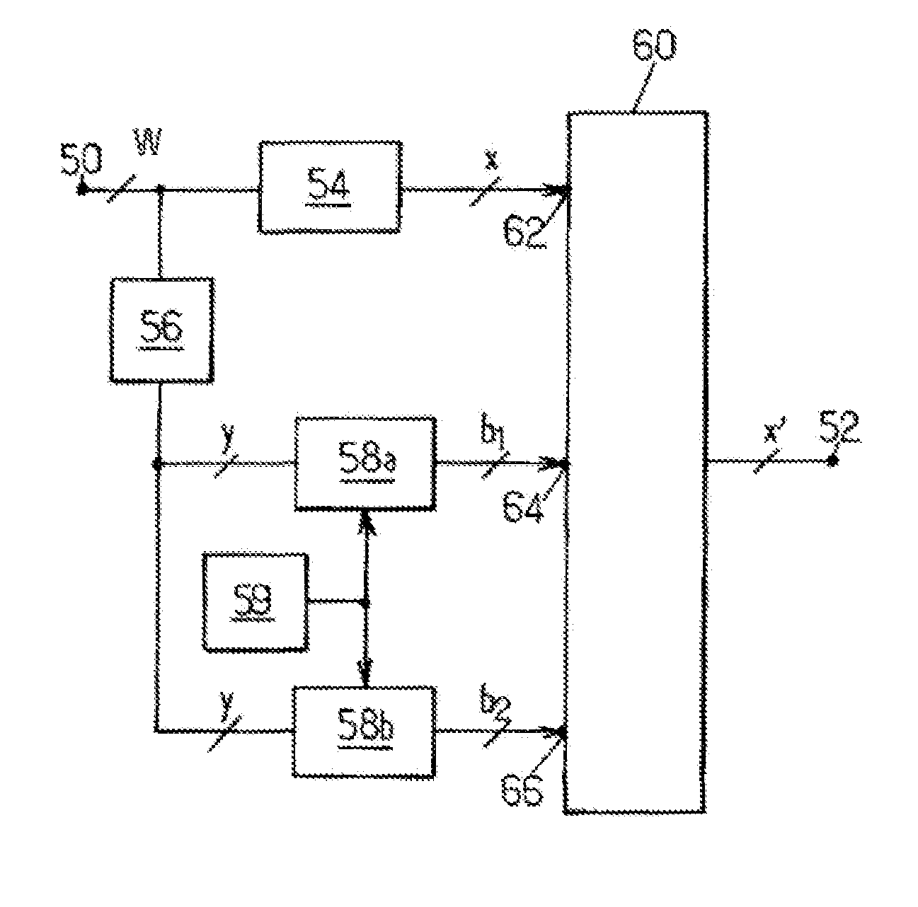
[0056]FIG. 2 shows a block diagram of a requantization circuit incorporating dithering according to the principle used by embodiments of the invention.

[0057]The requantization circuit comprises an input 50 for receiving an input sequence SEQin subdivided into periods of time T during which a digital word W encoded in a whole number IM of bits is received. It also comprises an output 52 outputting a sequence SEQout subdivided into periods of time T comprising digital words x′ each encoded in a whole number Ix of bits strictly less than IM. The requantization circuit therefore allows requantizing digital words M encoded in a given number of bits into digital words x′ encoded in a smaller number of bits.

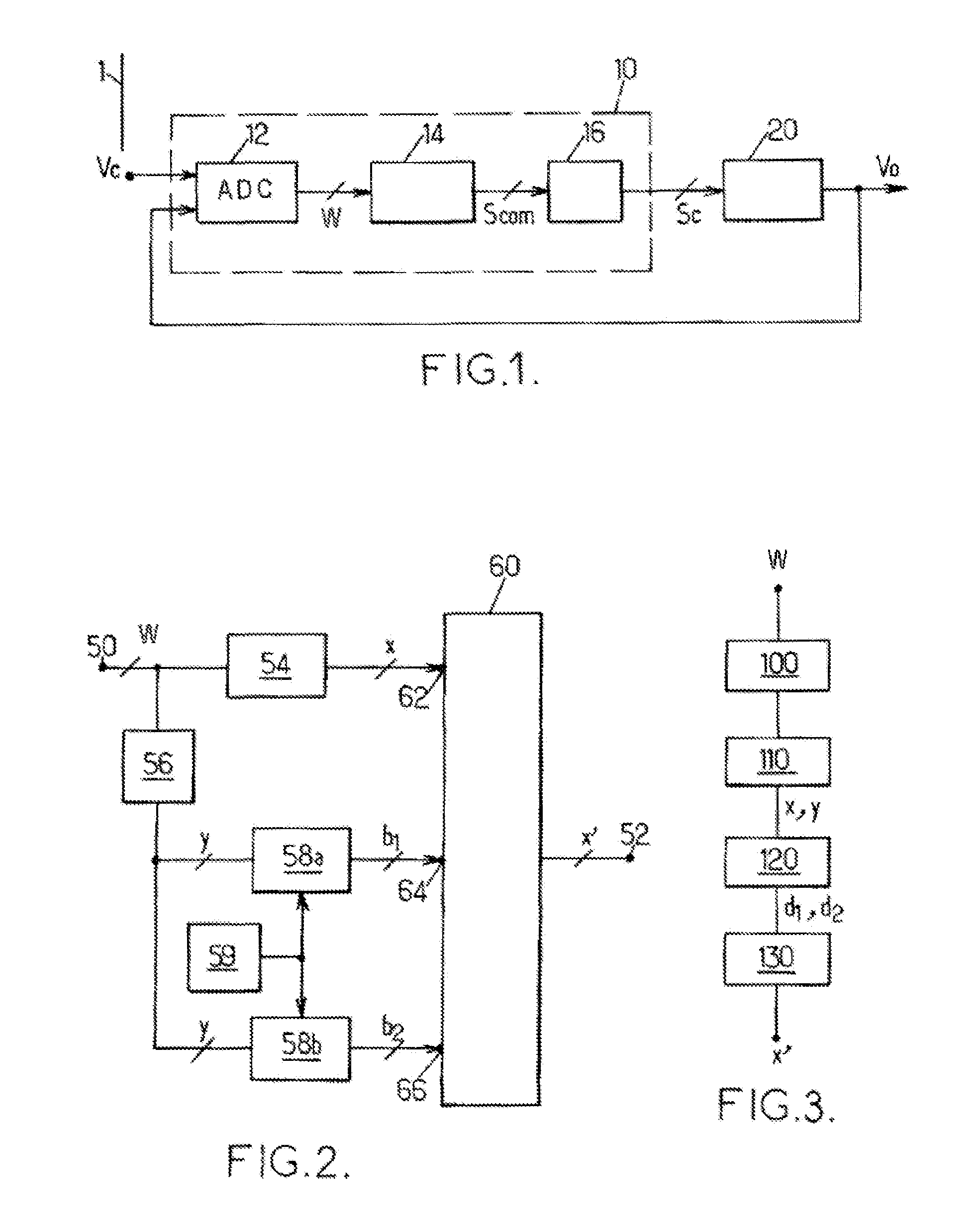
[0058]The input sequence SEQin is typically provided by the regulator 10 of the switched-mode power supply 1 or alternatively by the digital signal output from the analog-to-digital converter 12.

[0059]The output sequence SEQout can advantageously be directed to the input of the waveform...


PUM


Abstract

The invention relates to the digital signal requantization, at a given quantization step size, of a first word received in a first period of time and encoded in a first number of bits, into a second word, with a quantization error equal to a third number. A sequence of third words is outputted, equal to the second word, with the sequence subdivided into a first group comprising a number of third words that is equal to the third number and a second group of third words. Before outputting them, the correction means adds a least significant bit to the third words of the first group and adds or subtracts least significant bits to or from the third words of the second group, such that the sum of the least significant bits added to and subtracted from the second group is zero.

Description

TECHNICAL DOMAIN[0001]The present invention relates in general to the quantization of digital signals, and in particular to the reduction of undesirable low-frequency components introduced during this operation.[0002]The invention has applications in particular in the implementation of controllers for switched-mode power supplies used, for example, in equipment comprising microprocessors, such as computers, embedded systems, etc. In such an application, the controller is intended to regulate the output voltage of the power supply.TECHNOLOGICAL BACKGROUND[0003]FIG. 1 shows a schematic diagram of a switched-mode power supply 1 able to output an electrical voltage signal V0. The power supply 1 has a controller 10 comprising a first input for receiving the voltage V0 and a second input for receiving a reference voltage Vc, and an output for outputting a control signal Sc. The controller 10 itself comprises an analog-to-digital converter 12, followed by a regulator 14 implementing a cont...

Claims


Application Information

Patent Timeline
Patent Type & Authority Applications(United States)
IPC IPC(8): H03M7/00
CPCH03M7/3002
Inventor CLIQUENNOIS, SEBASTIEN
Owner TELEFON AB LM ERICSSON (PUBL)
Why Eureka
Try Eureka