Fixation control device and method for controlling the fixation of an eye

Active Publication Date: 2012-05-31
CARL ZEISS MEDITEC AG
View PDF2 Cites 35 Cited by
  • Summary
  • Abstract
  • Description
  • Claims
  • Application Information

AI Technical Summary

Benefits of technology

[0009]It is the object of the invention to improve an ophthalmological instrument of the type mentioned above and methods for m

Problems solved by technology

However, particularly over longer periods of time, there is an increasing likelihood that the patient will fail to maintain the state of fixation.
Lack of certainty with regard to fixation often leads to dispersions in diagnostic or therapeutic findings.
It is particularly problematic to maintain and monitor fixation in children, blind persons and persons with other kinds of disabilities.
Consequently, the image-taking frequency has an upper limit, for one, because of the lengthy readout of the sensor and, for another, because the subsequent ev

Method used


Image

  • Fixation control device and method for controlling the fixation of an eye
  • Fixation control device and method for controlling the fixation of an eye
  • Fixation control device and method for controlling the fixation of an eye

Examples


Embodiment Construction

[0047]It is to be understood that the figures and descriptions of the present invention have been simplified to illustrate elements that are relevant for a clear understanding of the present invention, while eliminating, for purposes of clarity, many other elements which are conventional in this art. Those of ordinary skill in the art will recognize that other elements are desirable for implementing the present invention. However, because such elements are well known in the art, and because they do not facilitate a better understanding of the present invention, a discussion of such elements is not provided herein.

[0048]The present invention will now be described in detail on the basis of exemplary embodiments.

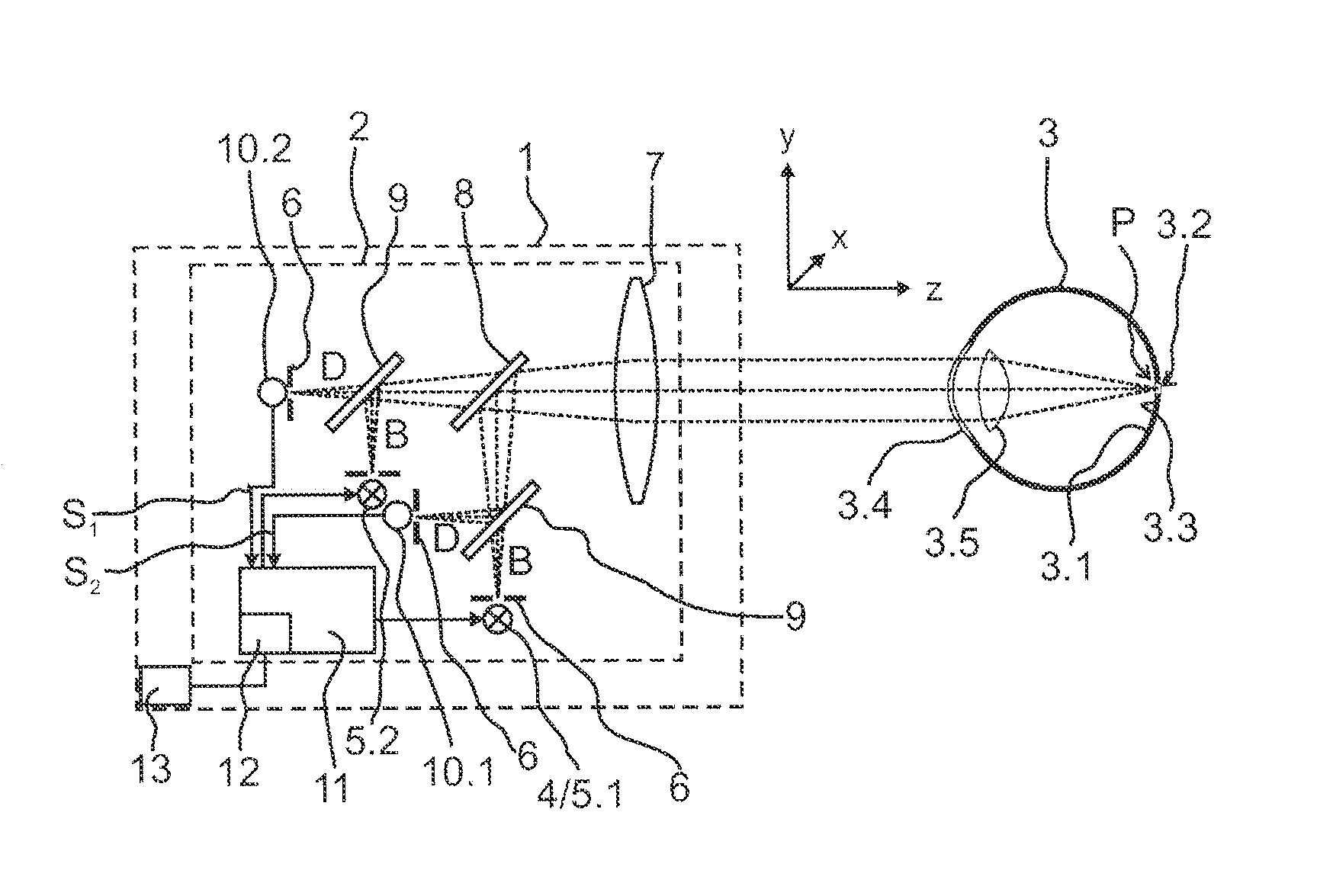
[0049]FIG. 1 is a schematic diagram showing an ophthalmological instrument 1, for example, a refractive laser, having a fixation monitoring device 2 for monitoring the fixation of an eye 3. The fixation monitoring device 2 comprises, for example, an approximately point-shaped f...


PUM


Abstract

With some ophthalmological instruments, the patient to be examined or treated needs to gaze in a defined direction. Accordingly, the operator needs the most objective possible information as to whether the patient actually fixates the fixating target or when this may no longer be the case. The invention makes it possible to monitor fixation economically with a short reaction time and with high accuracy. Monitoring of the fixation of an eye is accomplished in an economical manner with a short reaction time and high accuracy through spectroscopic detection of fixation, particularly by identifying a reflection at the fovea or foveola based on different reflectance factors compared to the rest of the retina.

Description

[0001]The present application claims priority from PCT Patent Application No. PCT / EP2010 / 058854 on Jun. 22, 2010, which claims priority from German Patent Application No. DE 10 2009 030 465.7 filed on Jun. 23, 2009, the disclosures of which are incorporated herein by reference in their entirety.BACKGROUND OF THE INVENTION[0002]1. Field of the Invention[0003]The invention is directed to a fixation monitoring device for an ophthalmological instrument, having a fixating light source for visible light and optics for imaging the fixating light source on a fundus of an eye and to a method for monitoring fixation of the eye.[0004]2. Description of Related Art[0005]With some ophthalmological instruments the patient to be examined or treated needs to gaze in a defined direction. As a rule, this orientation is decisive for the correctness of measurement or therapy and, therefore, for successful treatment. This is particularly true for refractometers, wavefront aberrometers and refractive lase...

Claims


Application Information

Patent Timeline
IPC IPC(8): A61B3/113A61B3/12A61B3/14A61B3/10
CPCA61B3/113
Inventor BERGT, MICHAELSTOBRAWA, GREGORSLUYTERMAN VAN LANGEWEYDE, GEORGMARK, BISCHOFF
Owner CARL ZEISS MEDITEC AG
Why Eureka
Try Eureka