
Method and System for Adaptive Interpolation in Digital Video Coding

Inactive Publication Date: 2012-05-31
KOSSENTINI FAOUZI +4
View PDF2 Cites 87 Cited by
  • Summary
  • Abstract
  • Description
  • Claims
  • Application Information

AI Technical Summary

Benefits of technology

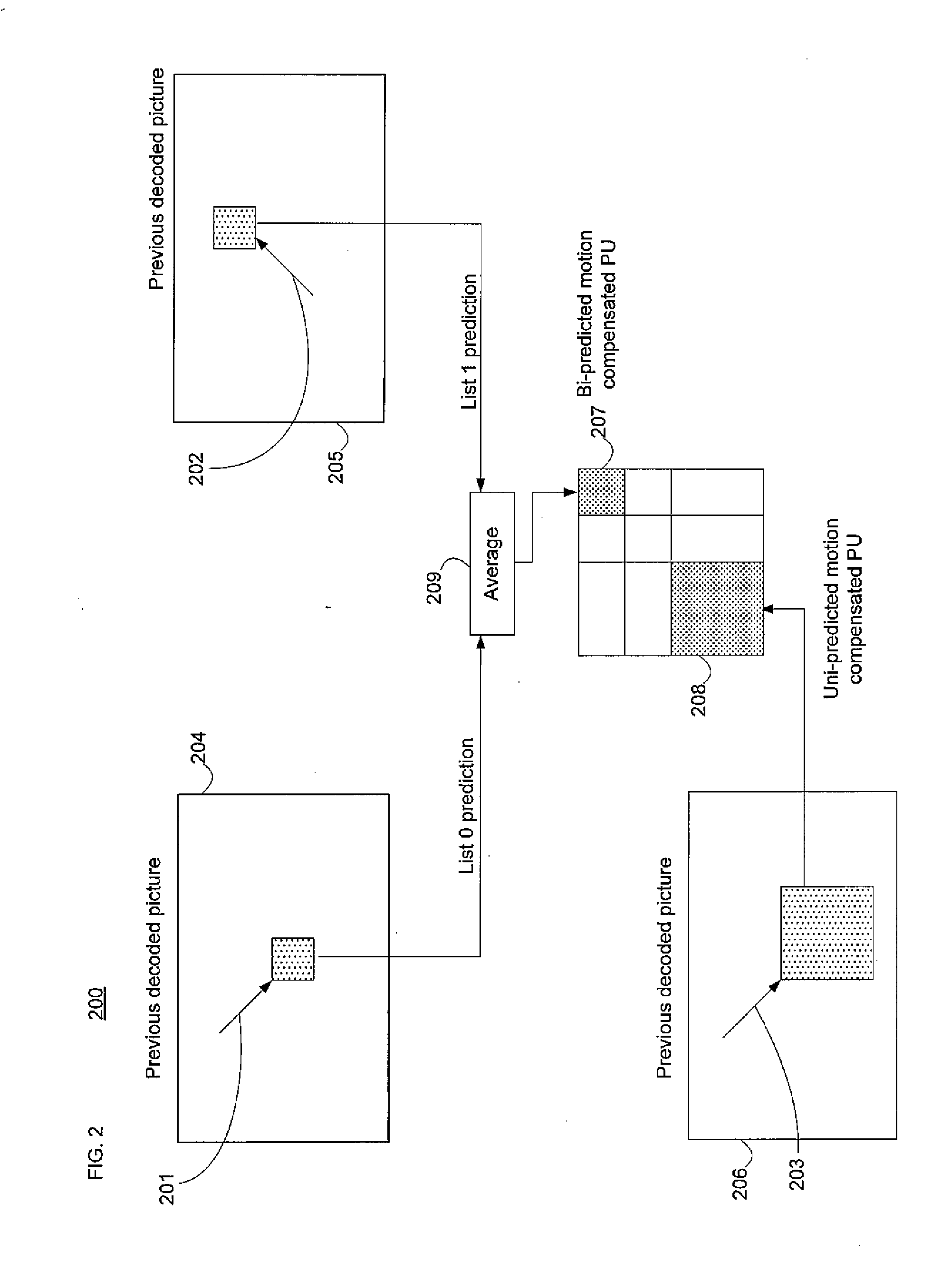
[0045]The filter with n×m coefficients may be specified, for example, by n×m coefficients, by (n×m) / 2 coefficients (taking advantage of symmetry effects), or, according to one aspect of the invention, by two one-dimensional (1D) filters with n and m coefficients, respectively. The fewer filter coefficients are used to specify the filter, the less flexibility an encoder has in optimizing the filter, and the fewer bits are potentially required for describing the 2D filter. However, the more filter coefficients that are used, the better the interpolation may be.

Problems solved by technology

However, neither WD3 nor other proposals allow, for all sub-sample positions, for the selection of different filter lengths for the horizontal and vertical filtering stages (i.e., 2D separable filters with rectangular and non-square regions of support).
Similarly, in certain hard implementation architectures, where line buffers are expensive (i.e., as they may be implemented on fast on-chip memory), shorter vertical interpolation filters can reduce memory requirements.
While the above technique provides better performance than that of H.264, one disadvantage is that its performance is not consistently good for all types of video content.
A disadvantage of this scheme is that even if a newly-generated filter (corresponding to a specific sub-sample position) would not produce better quality than the corresponding H.264 fixed filter, it would still be included in the bitstream, wasting bits, which would in turn lead to a decrease in overall coding efficiency and (assuming a fixed bit budget) a reduction in reproduced video quality.
Another shortcoming is the lower coding efficiency even when only pre-defined filters are in use due to the lack of n×m filters at diagonal sub-sample positions.

Method used


Image

  • Method and System for Adaptive Interpolation in Digital Video Coding
  • Method and System for Adaptive Interpolation in Digital Video Coding
  • Method and System for Adaptive Interpolation in Digital Video Coding

Examples


Embodiment Construction

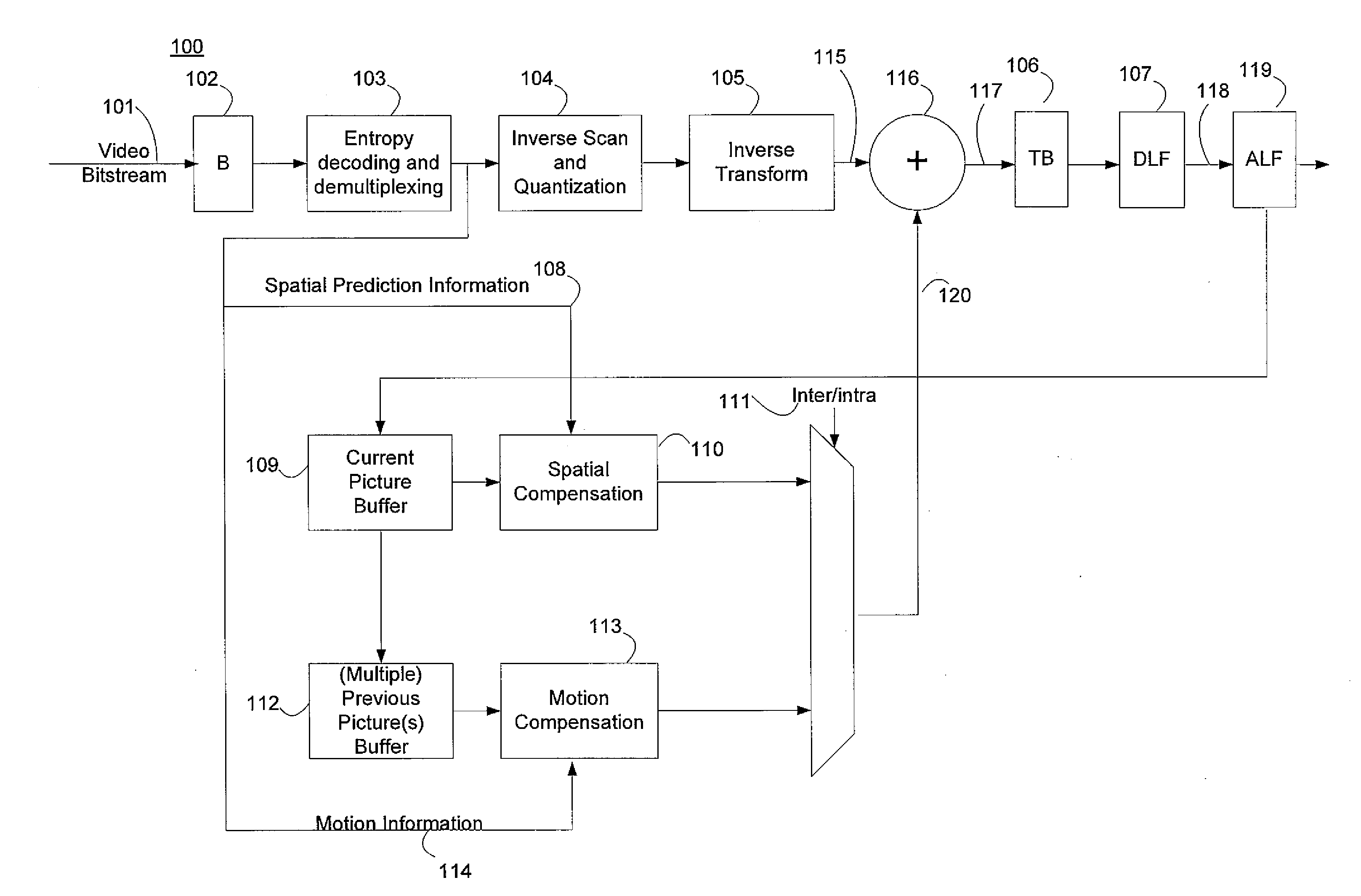
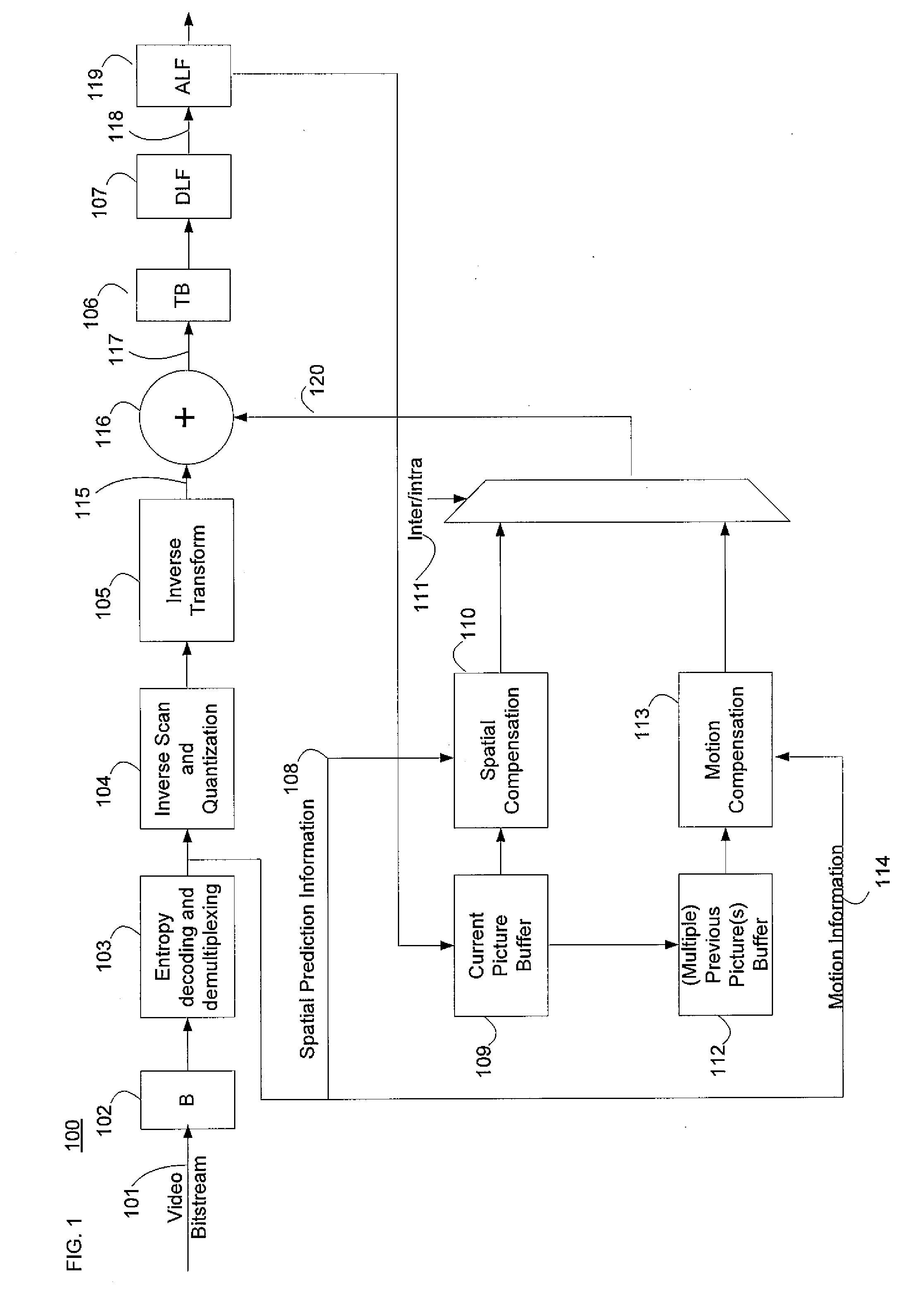
[0078]In the following description, details are set forth to provide an understanding of the invention. In some instances, certain software, circuits, structures and methods have not been described or shown in detail in order not to obscure the invention. The term “data processing system” is used herein to refer to any machine for processing data, including the computer systems, wireless devices, and network arrangements described herein. The present invention may be implemented in any computer programming language provided that the operating system of the data processing system provides the facilities that may support the requirements of the present invention. Any limitations presented would be a result of a particular type of operating system or computer programming language and would not be a limitation of the present invention. The present invention may also be implemented in hardware or in a combination of hardware and software.

[0079]The present invention relates to adaptive in...


PUM


Abstract

Disclosed are techniques for adaptive interpolation filtering of luminance and chrominance samples in the context of motion compensation in video encoding or decoding. A two-dimensional interpolation filter of n×m coefficients may be separable, i.e., it may be separated into two one-dimensional filters with m and n coefficients, respectively. The bitstream may include, per video unit and sub-sample position, information indicating whether to use a newly-generated, a cached, or a default filter that may be a separable two-dimensional filter. The information may be structured in a way that takes advantage of the two-dimensional filter being separable. When a newly-generated filter is signalled, the bitstream may contain information pertaining to the characteristics of the newly-generated filter, such as its coefficients. A decoder may fetch this information from the bitstream to create the filters which are applied to samples of the video unit. An encoder may create a bitstream as described.

Description

[0001]This application claims priority from U.S. Provisional Patent Application No. 61 / 417,498, filed Nov. 29, 2010, and incorporated herein by reference, and from U.S. Provisional Patent Application No. 61 / 500,295, filed Jun. 23, 2011, and incorporated herein by reference.FIELD OF THE INVENTION[0002]This invention relates to the field of video compression, and more specifically, to a method and system for adaptive interpolation in the context of motion compensation in video encoding and / or decoding.BACKGROUND OF THE INVENTION[0003]Digital video capabilities can be incorporated into a wide range of devices, including digital televisions, digital direct broadcast systems, wireless broadcast systems, personal digital assistants (PDAs), laptop or desktop computers, video cameras, digital recording devices, video gaming devices, video game consoles, cellular or satellite radio telephones, and the like. Digital video devices may implement video compression techniques, such as those descr...

Claims


Application Information

Patent Timeline
IPC IPC(8): H04N7/26
CPCH04N19/117H04N19/463H04N19/523H04N19/186H04N19/137
Inventor KOSSENTINI, FAOUZIMAHDI, NADERBEN AYED, MOHAMED-ALIGUERMAZI, HASSENHOROWITZ, MICHAEL
Owner KOSSENTINI FAOUZI
Learn More