Ridge waveguide serial interferometers

a serial interferometer and waveguide technology, applied in the direction of optical waveguide light guide, instruments, optics, etc., can solve the problems of varying the performance of semiconductor mzi, high manufacturing cost of lockers, and large footprint of arrangement inside compact optical telecommunications packages

Active Publication Date: 2012-05-31
LUMENTUM TECH UK LTD
View PDF2 Cites 22 Cited by
  • Summary
  • Abstract
  • Description
  • Claims
  • Application Information

AI Technical Summary

Benefits of technology

[0013]An input section may be coupled to the first mode conversion section at an end distal from the intermediate section, and is adapted to substantially transmit a fundamental mode. An output section may be coupled to the second mode conversion section at an end distal from the intermediate section, and is adapted to substantially transmit a fundamental mode and a higher order mode.
[0014]The interferometer may additionally comprise a Mach-Zehnder interferometer section. The interferometer may additionally comprise an electrical control system.

Problems solved by technology

Such arrangements have a sizable footprint inside a compact optical telecommunications package.
Further, such lockers are expensive to manufacture, not least due to the precision require in package assembly in order to accurately align each optical element.
However, disadvantageously the performance of the semiconductor MZI varies as a function of temperature.
Further, manufacturing yield is vulnerable to the manufacturing tolerances of the optical splitter and recombiner.

Method used


Image

  • Ridge waveguide serial interferometers
  • Ridge waveguide serial interferometers
  • Ridge waveguide serial interferometers

Examples


Embodiment Construction

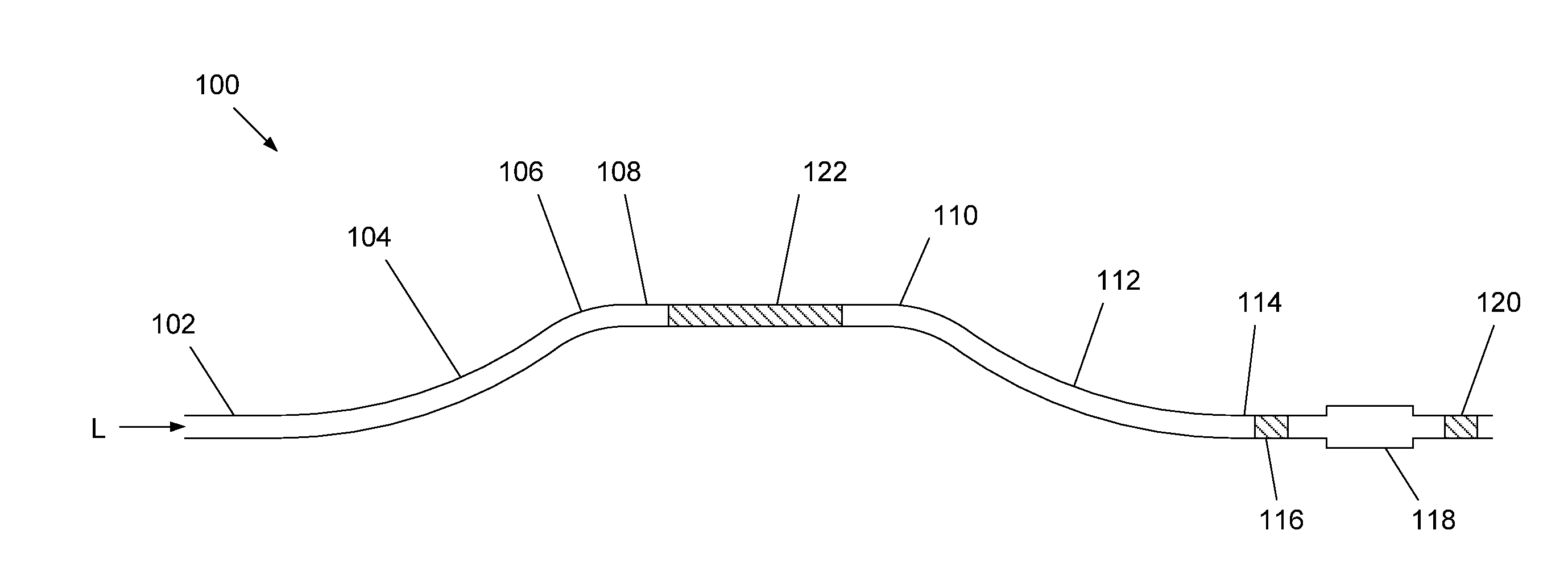
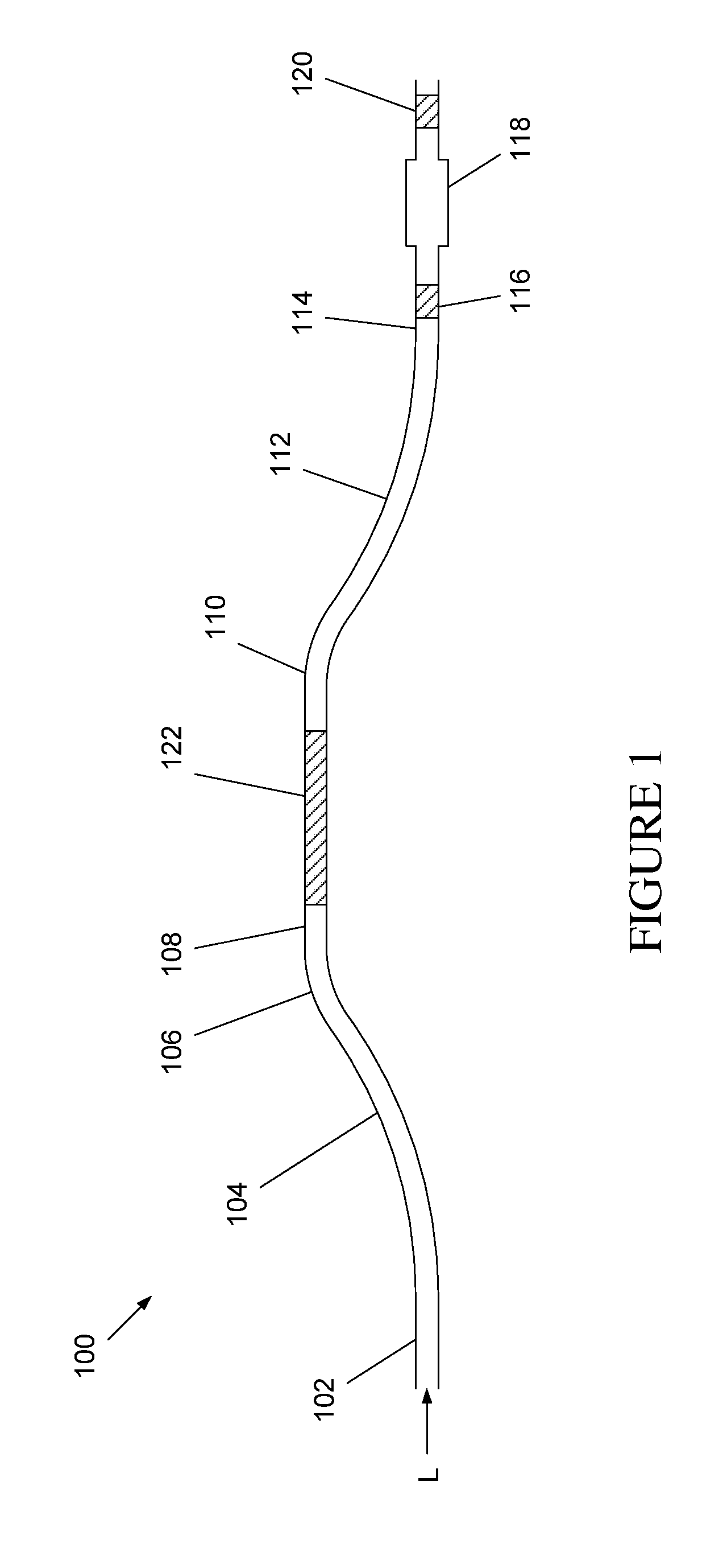
[0018]FIG. 1 illustrates a ridge waveguide serial interferometer 100 having an input waveguide 102, a first mode conserving section 104, a first mode conversion section 106, a intermediate section 108, a second mode conversion section 110, a second mode conserving section 112, an output waveguide 114, a first photodetector section 116, a mode filter 118, a second photodetector section 120 and a tuning electrode 122.

[0019]The components of the serial interferometer 100 form an optical circuit in which they are connected together in series along a common ridge waveguide. Advantageously the ridge waveguide is a tightly guiding ridge waveguide, which is commonly characterised by a significant refractive index difference between the guiding layer of the ridge waveguide and the lateral waveguide cladding (not shown). In use light L that is of the fundamental order mode of the ridge waveguide enters the interferometer 100 along the input waveguide 102 and propagates throughout the length o...


PUM


Abstract

In a ridge waveguide serial interferometer mode conversion is induced by a first mode conversion section, a phase difference between modes is introduced by propagation over a length of waveguide and optical interference is produced following further mode conversion induced in a second mode conversion section. The first mode conversion section has a first radius of curvature, which is equal to a second radius of curvature of the second mode conversion section. The ridge waveguide interferometer advantageously provides an equal phase dependency as a function of temperature.

Description

FIELD OF THE INVENTION[0001]The present invention relates to ridge waveguide serial interferometers.BACKGROUND OF THE INVENTION[0002]Optical applications commonly require the sensing and control of the wavelength of a light source. This is a particular concern within the optical telecommunications industry, in which light from several optical sources may be transmitted along a common optical fibre at different, closely spaced wavelengths. Such applications require optical sources producing light with a high level of wavelength stability and a narrow bandwidth.[0003]Lasers, such as semiconductor lasers, provide narrow bandwidth emission, but can drift and jump in wavelength. Accordingly, in applications in which wavelength stability is required, a wavelength locker is commonly employed, in which an optical wavelength sensor is used to monitor the emission wavelength from the optical source and an electrical feedback system provides control of the optical source in correspondence with...

Claims


Application Information

Patent Timeline
Patent Type & Authority Applications(United States)
IPC IPC(8): G02B6/26
CPCG02B6/12026G02B6/12028G02B6/2813G02B2006/12135G02B6/12007G02B6/14G02B6/1228G02B6/02095G02B2006/12159
Inventor BOUDREAU, MARCELBETTY, IAN BRIANWATSON, CHRISTOPHER
Owner LUMENTUM TECH UK LTD
Why Eureka
Try Eureka