Battery set package

a battery and set technology, applied in the field of battery set packages, can solve the problems of battery overheating, explosion, and even rupture, and achieve the effects of reducing the weight of the complete battery set package, enhancing the structural rigidity of the package, and reducing the size of the battery set packag

Inactive Publication Date: 2012-05-31
IND TECH RES INST
View PDF3 Cites 17 Cited by
  • Summary
  • Abstract
  • Description
  • Claims
  • Application Information

AI Technical Summary

Benefits of technology

[0008]The present disclosure provides a battery set package with sandwich structure, by that not only the structural rigidity of the package is enhanced, but also the major portions of the batteries mounted inside the package are exposed and thus can be cooled down by air flows of natural convection, especially when the battery set package is mounted on a vehicle, the batteries can be fully cooled down by the wind resulting from the moving of the vehicle without requiring any additional cooling device, and consequently, the battery set package is advantageous in that: the weight of the complete battery set package can be greatly reduced with comparatively smaller space required for installment, and the probability of malfunction is greatly reduced as well as the manufacturing cost is greatly reduced.

Problems solved by technology

Nevertheless, although this is useful in applications where high currents are required, a too-rapid discharge of a lithium battery can result in overheating of the battery, rupture, and even explosion.
Moreover, because of the above risks, it is generally not recommended to build an ultra-high-power lithium battery cell, since an ultra-high-power lithium battery cell is usually large in size so that it may not be able to dissipate heat effectively, thereby causing the battery cell to overheat and possibly explode.
Thus, for safety consideration, the maximum size of the lithium battery cell to be built is restricted.
However, also under the forgoing restriction, such battery demand in BEV application can only be fulfilled by the use of lithium batteries in series-parallel connection.
However, for receiving all the battery cells therein, as the filly closed battery set package not only should be built larger enough, but also it should be built with sufficient structural rigidity, consequently the weight of the battery set package itself can be very heavy.
Moreover, it is noted that the whole battery set package is required to be built differently in size so as to be adapted for package battery cells of different size; and the use of cooling device in the aforesaid battery set package for cooling the battery cells not only may not be cost effective in view of the manufacturing cost and power consumption, but also the malfunction probability of the battery set package is increased since any malfunctioning of the cooling device may cause the temperature of its battery cells to increase rapidly and thus stop discharging.
That is, the conventional vehicle-mounted battery set package is disadvantageous in that: the weight of the complete battery set package can be very heavy as the battery set package itself may occupy a comparatively large space for installment; and structure of the battery set package may be very complex with many parts and thus its may be very costly to build; the battery set package is not flexible to be adapted for receiving batteries of different sizes; and the probability of malfunction is high, and so on.
Nevertheless, all the aforesaid battery set packages are still suffered by the same disadvantages of those conventional battery set package, including: the build of the battery set package is heavy and bulky; poor cooling efficiency, high cooling cost, and so on

Method used


Image

  • Battery set package
  • Battery set package
  • Battery set package

Examples


Embodiment Construction

[0023]For your esteemed members of reviewing committee to further understand and recognize the fulfilled functions and structural characteristics of the disclosure, several exemplary embodiments cooperating with detailed description are presented as the follows.

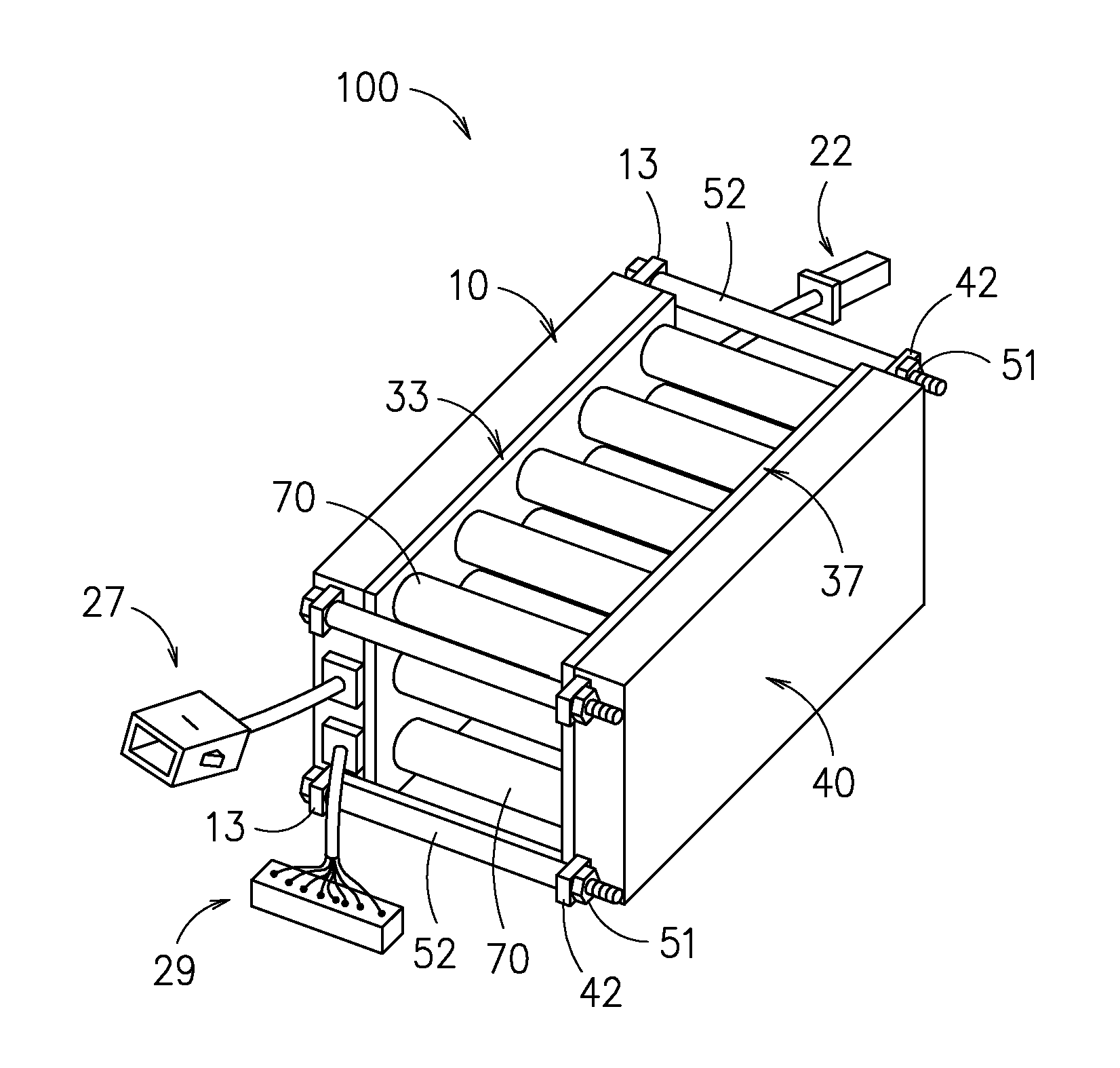
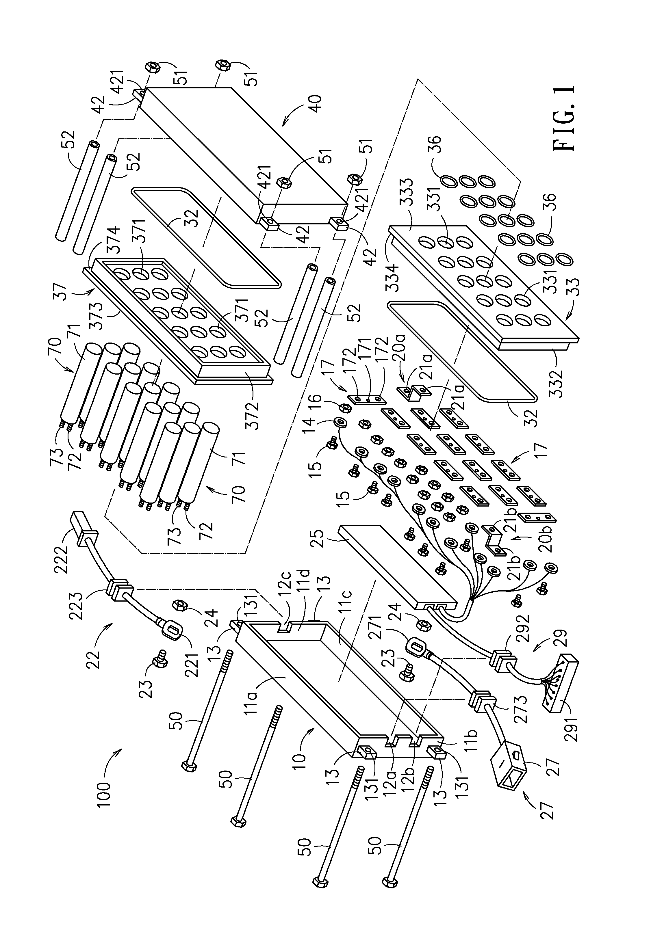
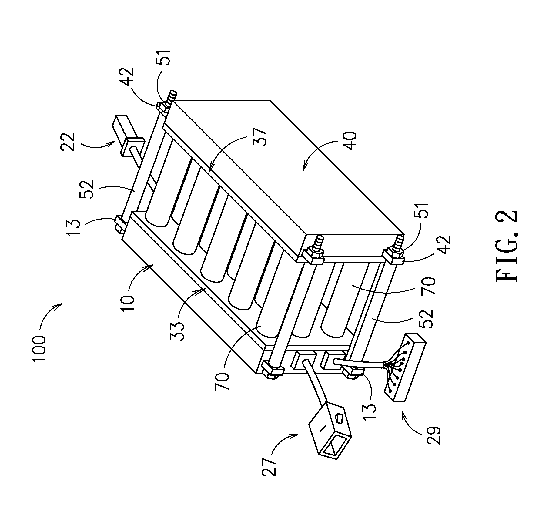
[0024]Please refer to FIG. 1 and FIG. 2, which show a battery set package according to a first embodiment of the present disclosure. As shown in FIG. 1 and FIG. 2, the battery set package 100 comprises: a plurality of battery cells 70, a first bracket 33, a second bracket 37, a first shell 10 and a second shell 40, in which the plural battery cells 70 are sandwiched and hold between the first bracket 33 and the second bracket 37, while the assembly of the plural battery cells 70 sandwiched between the first bracket 33 and the second bracket 37 is further being sandwiched between the first shell 10 and the second shell 40, forming a battery set package with sandwich structure.

[0025]Moreover, each of the plural battery cells 70...


PUM

PropertyMeasurementUnit
specific lengthaaaaaaaaaa
clamping forcesaaaaaaaaaa
outer diameteraaaaaaaaaa

Abstract

A battery set package is disclosed, which comprises: a plurality of battery cells, each being configured with a frame of a specific length that has two terminals defined at the two opposite longitudinal ends of the frame; two brackets, disposed respectively at the two opposite terminals of the frame for allowing the plural battery cells to be sandwiched between the two brackets; two shells, respectively mounted on the both side of the two brackets; and a plurality of fixtures, for exerting clamping forces in a direction parallel with the longitudinal direction of the frame to the two shells so as to press the two shells to move toward each other and thus fixedly secured the two brackets along with the plural battery cells between the two shells.

Description

TECHNICAL FIELD[0001]The present disclosure relates to a battery set package, and more particularly, to a battery set package with sandwich structure, by that not only the structural rigidity of the package is enhanced, but also the major portions of the battery cells mounted inside the package are exposed and thus can be cooled down by air flows of natural convection, especially when the battery set package is mounted on a vehicle, the battery cells can be fully cooled down by the wind resulting from the moving of the vehicle without requiring any additional cooling device, and consequently, the battery set package is advantageous in that: the weight of the complete battery set package can be greatly reduced with comparatively smaller space required for installment, and the probability of malfunction is greatly reduced as well as the manufacturing cost is greatly reduced.TECHNICAL BACKGROUND[0002]Lithium batteries can provide extremely high currents and can discharge very rapidly w...

Claims


Application Information

Patent Timeline
Patent Type & Authority Applications(United States)
IPC IPC(8): H01M10/02H01M2/02H01M50/213H01M50/24H01M50/264H01M50/505H01M50/509H01M50/522
CPCB60K1/04B60K11/06B60Y2200/12H01M2/1077H01M2/206B60K2001/005Y02E60/10B62J43/16B62K2204/00H01M50/505H01M50/213H01M50/264H01M50/509H01M50/522H01M50/24
Inventor GU, HUAN-LUNGCHANG, JYH-CHUN
Owner IND TECH RES INST
Why Eureka
Try Eureka