Garden shears

Inactive Publication Date: 2012-06-07
HO CHENG GARDEN TOOLS
View PDF11 Cites 12 Cited by
  • Summary
  • Abstract
  • Description
  • Claims
  • Application Information

AI Technical Summary

Benefits of technology

[0008]The primary components of the present invention only include two cutter bases, an anvil, a cutter plate and an operating arm. Thus, the present invention has reduced components and costs. Further, the operating handle extends the action arm of the operating arm when the driving toothed edge of the operating arm drives the driven rack of the cutter plate. Thus, the present invention is simple in structure and labor-saving.
[0009]Furthermore, the roller wheel is positioned between the restricting holes of the two supporting plates to slide in the positioning slot of the cutter plate. Thus, when the cutter blade is driven by the operating arm to move upwards or downwards, the movement of the cutter plate is smoother due to the rolling of the roller wheel, thereby facilitating the cutting action of the cutter plate.

Problems solved by technology

Since the conventional labor-saving garden shears has a complicated structure, the production and assembly thereof requires significant time and effort and production costs are consequently high.

Method used


Image

  • Garden shears
  • Garden shears
  • Garden shears

Examples


Embodiment Construction

[0016]In order to better understand the objectives, features and effects of the present invention, a detailed description will be made hereinafter with reference to the accompanying drawings.

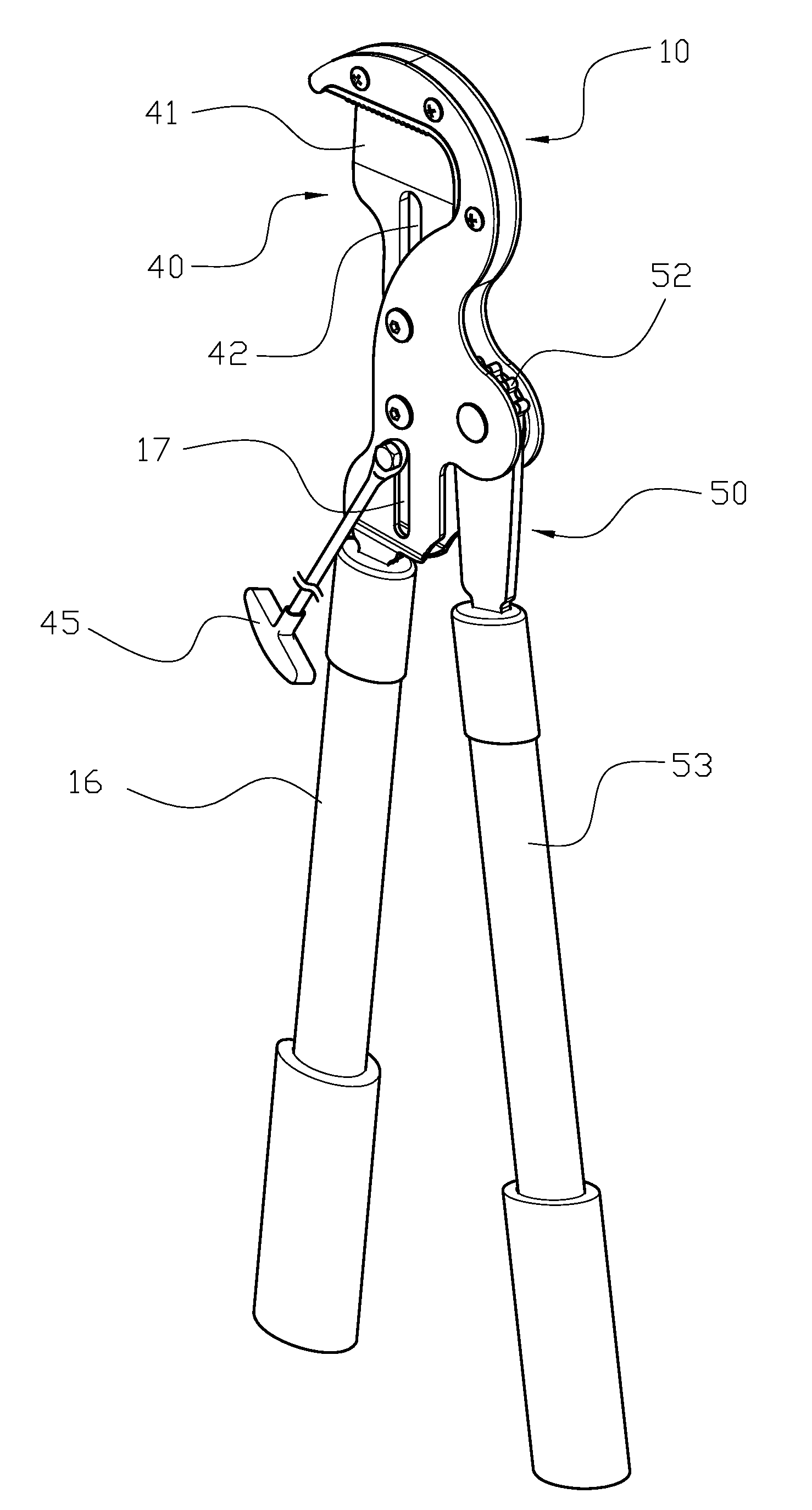
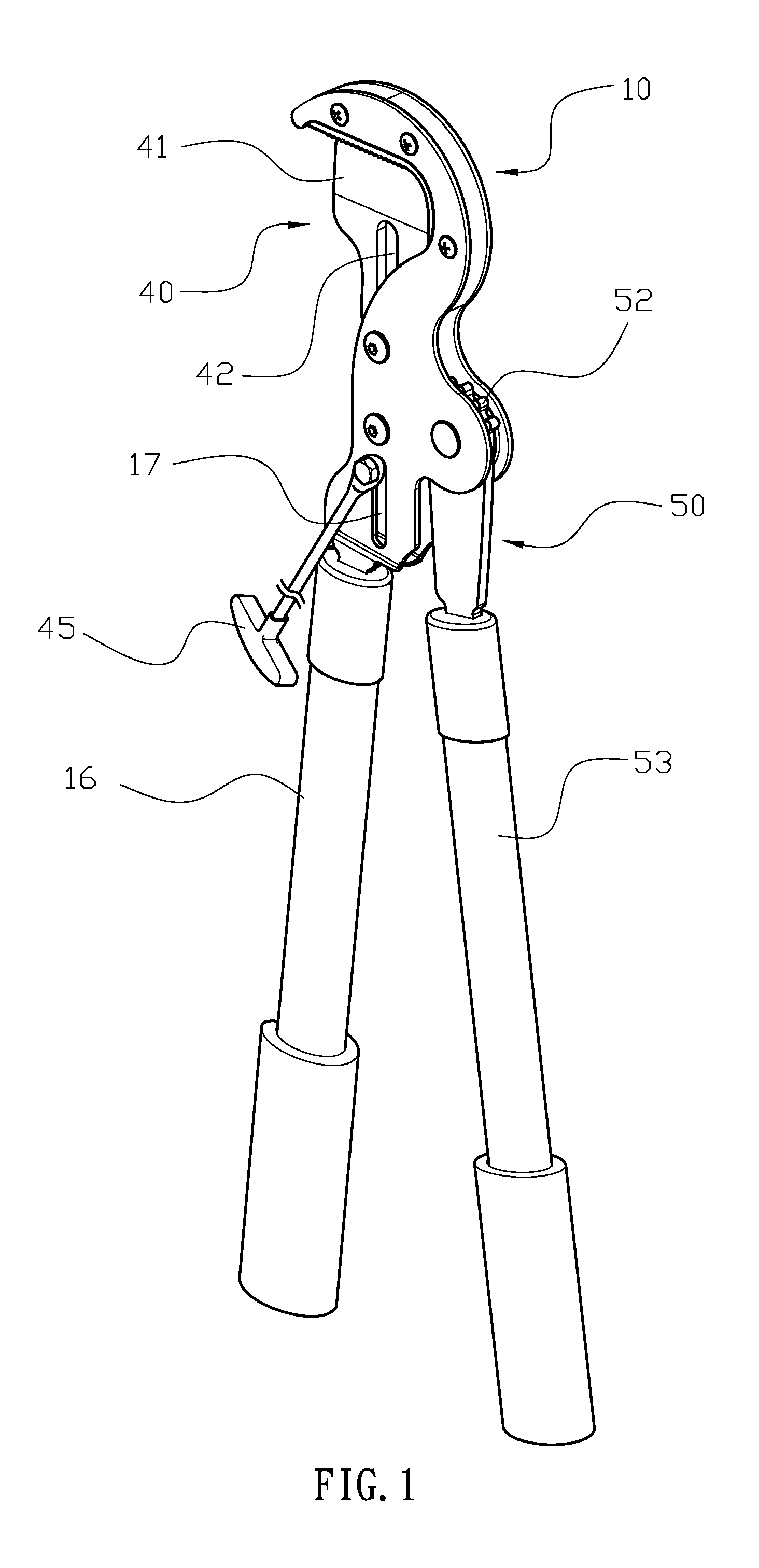
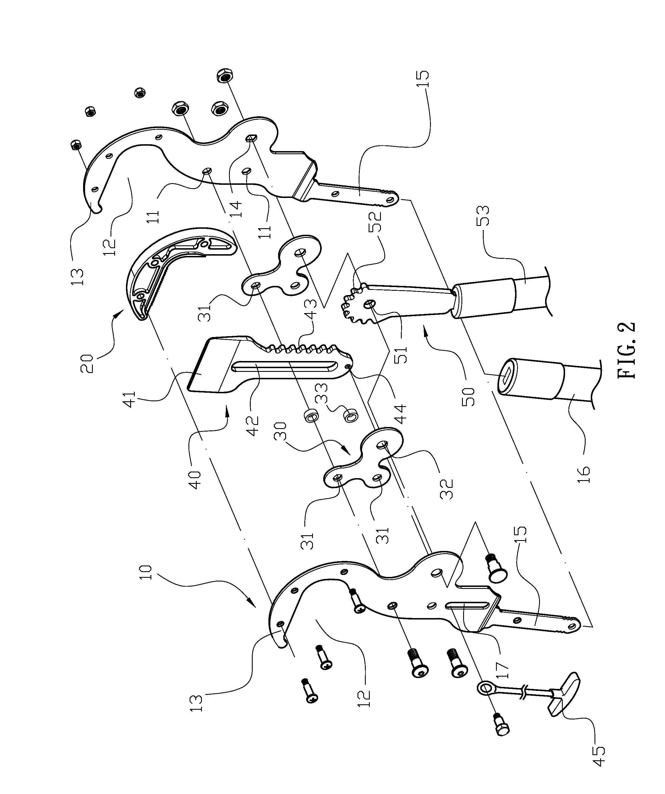
[0017]Please refer to FIGS. 1 and 2. An embodiment of the present invention provides a garden shears with a driving mechanism, which includes two cutter bases (10), an anvil (20) cooperating with the cutter bases (10), two supporting plates (30), a cutter plate (40), and an operating arm (50). Each of the two cutter bases (10) is provided with at least two positioning holes (11) disposed in its respective central region. The upper portion of the cutter base (10) is shaped to have a lateral opening (12) with a top section (13) located above the lateral opening (12). A side of the cutter base (11) opposite the two positioning holes (11) is formed with a pivotal hole (14). The lower portion of the cutter base (10) is provided with a connecting section (15). The connecting section (15) is inserted i...


PUM


Abstract

A garden shears with a driving mechanism includes two cutter bases, an anvil cooperating with the cutter bases, two supporting plates, a cutter plate, and an operating arm. The two cutter bases face each other to form an accommodating space in which the anvil and the two supporting plates are sandwiched. The anvil is fixed to top sections of the two cutter bases. The cutter plate and the operating arm are sandwiched between the two supporting plates. A roller wheel is disposed in a positioning slot of the cutter blade and sandwiched between restricting holes of the two supporting plates. A pivotal hole of the operating arm is pivotally connected between pivotal holes of the two supporting plates in such a manner that a driving toothed edge of the operating arm is drivingly engaged with a driven rack of the cutter plate. A pull lever is fixed to a fixing portion provided on a lower portion of the cutter plate through an elongate slot of the cutter base.

Description

BACKGROUND OF THE INVENTION[0001]1. Field of the Invention[0002]The present invention relates to garden shears with a driving mechanism, and in particular to garden shears utilizing the lever principle and a toothed engagement to economize the force needed for performing a pruning action.[0003]2. Description of the Prior Art[0004]Since branches are suspended in midair, garden shears are a better choice for pruning branches rather than a handsaw. Some branches are, however, too thick and may be located at high positions, and as a result garden shears operated with a simple shearing action are unsatisfactory in this situation because the user has to exert a large force for pruning such branches. Thus, manufacturers in this art propose garden shears having a labor-saving mechanism to make the pruning action easier. However, existing garden shears having a labor-saving mechanism have a complicated structure, and so the production and assembly thereof requires significant time and work, ...

Claims


Application Information

Patent Timeline
IPC IPC(8): A01G3/08
CPCA01G3/021A01G3/0251
Inventor HUANG, YAO-CHUNG
Owner HO CHENG GARDEN TOOLS
Why Eureka
Try Eureka