Non-Degenerate Mode MEMS Gyroscope

a gyroscope and non-degenerate technology, applied in the field of microelectromechanical systems (mems) gyroscopes, can solve the problems of loss of sensitivity, output of the gyroscope, and serious problems of the baw gyroscope, and achieve the effect of reducing the quadrature error

Active Publication Date: 2012-06-07
ANALOG DEVICES INC
View PDF1 Cites 32 Cited by
  • Summary
  • Abstract
  • Description
  • Claims
  • Application Information

AI Technical Summary

Benefits of technology

[0028]The microelectromechanical systems (MEMS) gyroscope may include a servo circuit coupled to the drive circuit. The servo circuit may be configured to automatically adjust how the drive circuit differentially drives the at least two electrodes, so as to reduce a quadrature error.

Problems solved by technology

However, very slight manufacturing or material imperfections (“non-idealities”) in BAW gyroscopes pose serious problems.
For example, such non-idealities cause the resonant frequency of the drive mode of oscillation to be different than the resonant frequency of the sense mode of oscillation, leading to a loss of sensitivity (i.e., lower amplitude of oscillation in the sense mode for a given angular rate of rotation) and, more seriously, in phase errors, which cause an output from the gyroscope in the absence of rotation.
However, maintaining degeneracy is difficult in the case of high quality (Q) oscillators, due to the need for tight control of these parameters over time and despite variations in temperature of the bulk mass.

Method used


Image

  • Non-Degenerate Mode MEMS Gyroscope
  • Non-Degenerate Mode MEMS Gyroscope
  • Non-Degenerate Mode MEMS Gyroscope

Examples


Embodiment Construction

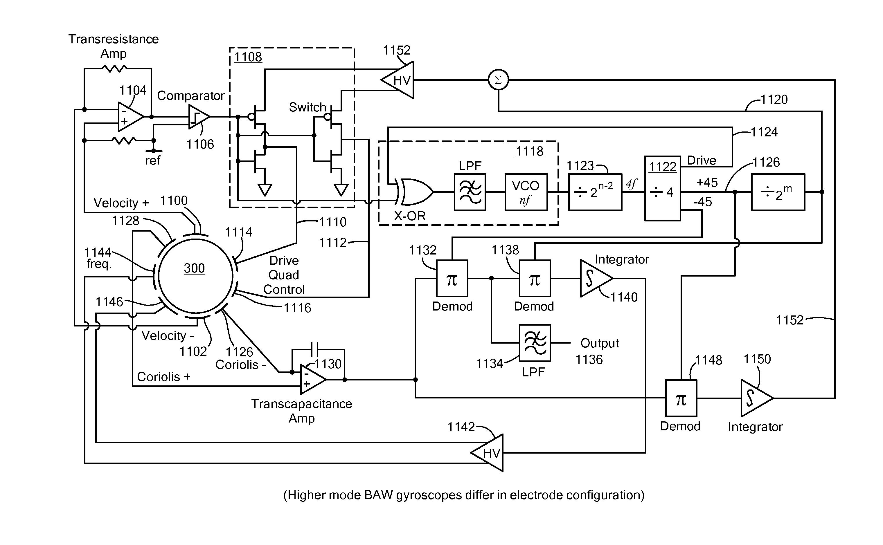
[0008]An embodiment of the present invention provides a microelectromechanical systems (MEMS) gyroscope. The gyroscope includes a substrate and a primary member attached to the substrate. The primary member is configured to vibrate in a first bulk acoustic mode at a drive frequency in response to a varying electrostatic signal. The primary member is also configured to vibrate in a second bulk acoustic mode at the drive frequency in response to the primary member being rotated about an axis. The second bulk acoustic mode is different than the first bulk acoustic mode. The first bulk acoustic mode and the second bulk acoustic mode are non-degenerate.

[0009]The second bulk acoustic mode may be characterized by a resonant frequency. The drive frequency may differ from the resonant frequency of the second bulk acoustic mode. The microelectromechanical systems (MEMS) gyroscope may also include a drive circuit and a servo circuit coupled to the drive circuit. The drive circuit may be config...


PUM


Abstract

Bulk acoustic wave (BAW) gyroscopes purposefully operate using non-degenerate modes, i.e., resonant frequencies of drive and sense modes are controlled so they are not identical. The resonant frequencies differ by a small controlled amount (Δf). The difference (Δf) is selected such that the loss of sensitivity, as a result of using non-degenerate modes, is modest. Non-degenerate operation can yield better bandwidth and improves signal-to-noise ratio (SNR) over comparable degenerate mode operation. Increasing Q of a BAW resonator facilitates trading bandwidth for increased SNR, thereby providing a combination of bandwidth and SNR that is better than that achievable from degenerate mode devices. In addition, a split electrode configuration facilitates minimizing quadrature errors in BAW resonators.

Description

CROSS REFERENCE TO RELATED APPLICATIONS[0001]This application claims the benefit of U.S. Provisional Patent Application No. 61 / 418,675, filed Dec. 1, 2010, titled “Non-Degenerate Shell-Type Gyroscope,” the entire contents of which are hereby incorporated by reference herein, for all purposes.TECHNICAL FIELD[0002]The present invention relates to microelectromechanical systems (MEMS) gyroscopes and, more particularly, to bulk acoustic wave (BAW) MEMS gyroscopes that operate in non-degenerate modes.BACKGROUND ART[0003]One type of conventional microelectromechanical systems (MEMS) gyroscope includes a proof mass suspended by springs within a support structure. A drive circuit causes the proof mass to oscillate (translate back and forth) in a plane of oscillation. Hence, this type of device is often referred to as a “shuttle-type gyroscope.” When the support structure is rotated in the plane of oscillation, the proof mass tends to continue oscillating in the plane but, as a result of the...

Claims


Application Information

Patent Timeline
Patent Type & Authority Applications(United States)
IPC IPC(8): G01P3/44H01L41/00
CPCG01C19/5698
Inventor JUDY, MICHAEL W.GEEN, JOHN A.JOHARI-GALLE, HOURI
Owner ANALOG DEVICES INC
Why Eureka
Try Eureka