Ultrasonic inspection equipment and ultrasonic inspection method

a technology of ultrasonic inspection and ultrasonic inspection, which is applied in the direction of instruments, specific gravity measurement, measurement devices, etc., can solve the problems of inability to successfully superimpose the two data on each other, disadvantageous to taking a huge amount of time for such correction work, and inability to confirm the correlation between the three-dimensional ultrasonic inspection data and the three-dimensional shape data, etc., to achieve the effect of facilitating the alignment of the display position of three-dimensional ultras

Inactive Publication Date: 2012-06-07
MITSUBISHI HITACHIPOWER SYST LTD
View PDF5 Cites 32 Cited by
  • Summary
  • Abstract
  • Description
  • Claims
  • Application Information

AI Technical Summary

Benefits of technology

[0020]An object of the present invention is to provide ultrasonic inspection equipment and method which facilitate alignment of display positions of three-dimensional ultrasonic inspection data and three-dimensional shape data, and which are capable of quickly discriminating between a defect echo and an inner-wall echo.
[0031]The above-described configuration facilitates the alignment of display positions of three-dimensional ultrasonic inspection data and three-dimensional shape data. This makes it possible to quickly discriminate between a defect echo and an inner-wall echo.
[0038]The above-described method facilitates the alignment of display positions of three-dimensional ultrasonic inspection data and three-dimensional shape data. This makes it possible to quickly discriminate between a defect echo and an inner-wall echo.
[0040]According to the present invention, the alignment of display positions of three-dimensional ultrasonic inspection data and three-dimensional shape data is facilitated. This makes it possible to quickly discriminate between a defect echo and an inner-wall echo.

Problems solved by technology

If the correction of display positions and the correction of display scales are not correctly performed, correlation of the three-dimensional ultrasonic inspection data with the three-dimensional shape data cannot be confirmed.
It is disadvantageous to take a huge amount of time for such correction work.
Accordingly, even if the coordinates of the origin point of the two-dimensional ultrasonic inspection data simply coincide with the coordinates of the origin point of the two-dimensional shape data, both of data cannot be successfully superimposed on each other.

Method used


Image

  • Ultrasonic inspection equipment and ultrasonic inspection method
  • Ultrasonic inspection equipment and ultrasonic inspection method
  • Ultrasonic inspection equipment and ultrasonic inspection method

Examples


Embodiment Construction

[0052]A configuration of ultrasonic inspection equipment and operation thereof according to one embodiment of the present invention will be described below with reference to FIGS. 1 through 11.

[0053]First of all, a configuration of ultrasonic inspection equipment according to this embodiment will be described with reference to FIG. 1.

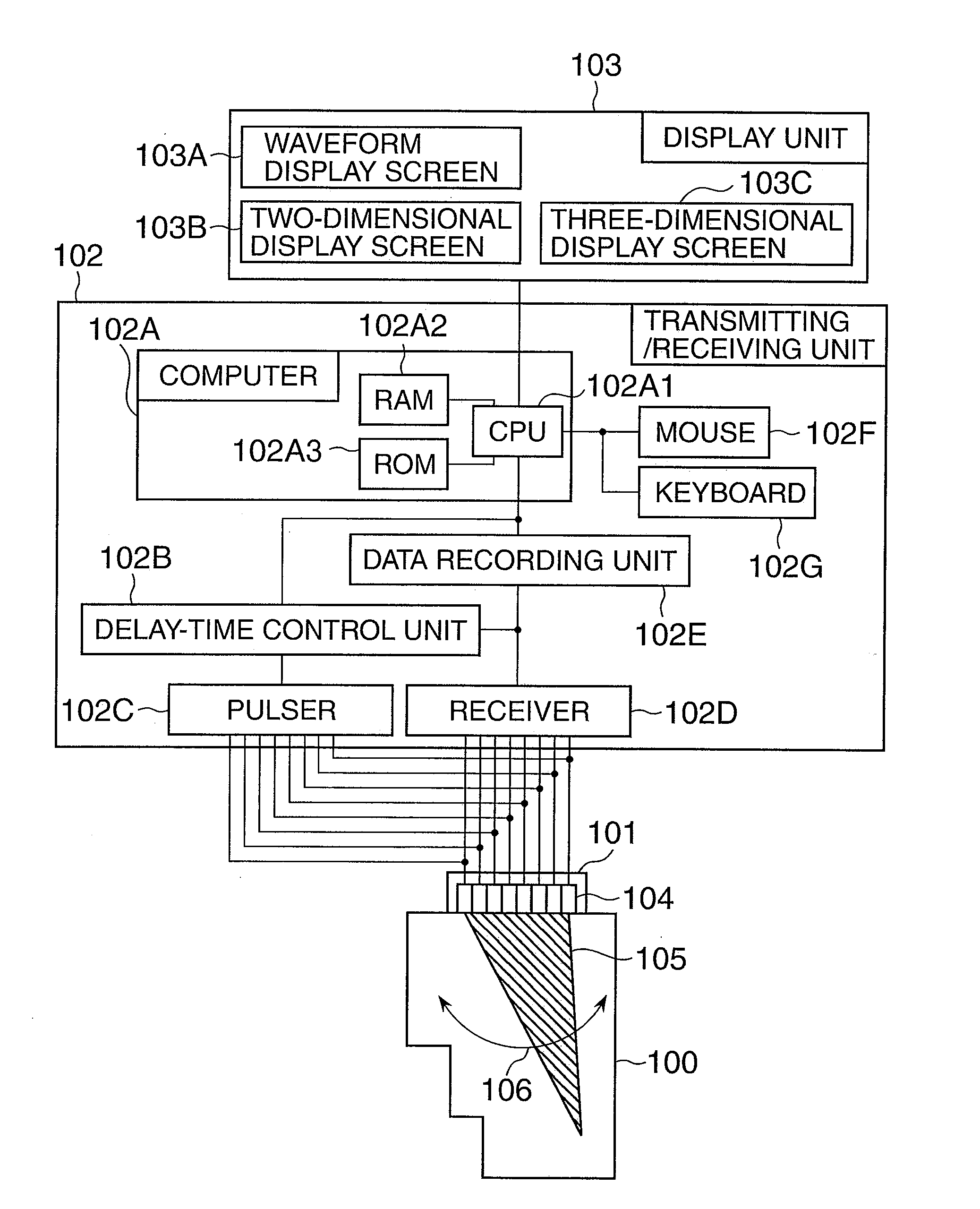
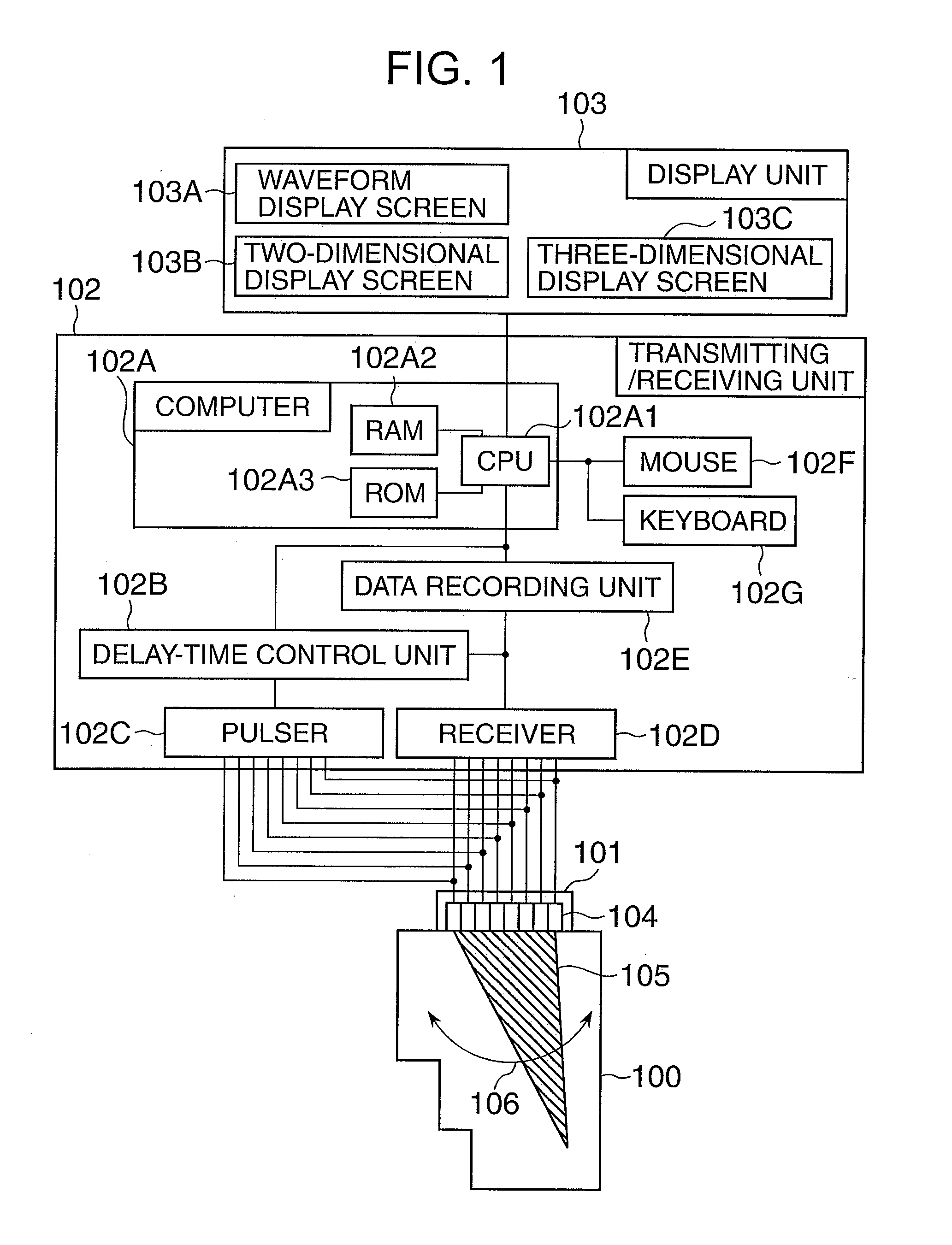
[0054]FIG. 1 is a system block diagram illustrating the configuration of the ultrasonic inspection equipment according to one embodiment of the present invention.

[0055]The ultrasonic inspection equipment according to this embodiment includes: an array-probe ultrasonic sensor 101 for emitting an ultrasonic wave toward a target to be inspected 100; a transmitting / receiving unit 102; and a display unit 103 for displaying a received signal and an inspection image.

[0056]As described in the figure, the array-probe ultrasonic sensor 101 is basically constituted of a plurality of piezoelectric vibration elements 104, each of which generates an ultrasonic wave a...


PUM

PropertyMeasurementUnit
piezoelectricaaaaaaaaaa
delay timeaaaaaaaaaa
image processingaaaaaaaaaa

Abstract

Ultrasonic inspection equipment facilitates alignment of display positions of three-dimensional ultrasonic inspection data and three-dimensional shape data, and quickly discriminates between a defect echo and an inner-wall echo. A computer 102A has a position correction function of correcting a relative display position between three-dimensional shape data and three-dimensional ultrasonic inspection data. A display position of the three-dimensional ultrasonic inspection data or that of the three-dimensional shape data is moved by a norm of a mean vector along the mean vector that is calculated from a plurality of vectors defined by a plurality of points selected in the three-dimensional ultrasonic inspection data and by a plurality of points selected in the three-dimensional shape data. The three-dimensional shape data and the three-dimensional ultrasonic inspection data are displayed in such a manner as to be superimposed on each other on a three-dimensional display unit 103C.

Description

[0001]This application is a continuation of U.S. patent application Ser. No. 12 / 472,873, filed May 27, 2009.BACKGROUND OF THE INVENTION[0002]1. Field of the Invention[0003]The present invention relates to ultrasonic inspection equipment and method for performing ultrasonic inspection that is a kind of non-destructive examination, and more particularly to ultrasonic inspection equipment and method that use an array-probe ultrasonic sensor.[0004]2. Description of the Related Art[0005]In the field of ultrasonic inspection methods for inspecting various kinds of structural materials, an inspection method for imaging an internal state of a target to be inspected in a short period of time with high accuracy to inspect the target has been developed in recent years. Such an inspection method for imaging is typified by a phased array method, a synthetic aperture focusing technique, and the like (for example, refer to non-patent document 1).[0006]The phased array method uses a so-called array...

Claims


Application Information

Patent Timeline
Patent Type & Authority Applications(United States)
IPC IPC(8): G01N29/00
CPCG01N29/06G06T19/20G01N29/04G10K11/00
Inventor KITAZAWA, SOKONO, NAOYUKIBABA, ATSUSHI
Owner MITSUBISHI HITACHIPOWER SYST LTD
Why Eureka
Try Eureka