Exhaust Gas Controlling Method of Engine

a technology of exhaust gas and control method, which is applied in the direction of electrical control, machine/engine, programme control, etc., to achieve the effect of improving the quality of exhaust gas and reducing fuel consumption

Active Publication Date: 2012-06-07
HYUNDAI MOTOR CO LTD +1
View PDF7 Cites 13 Cited by
  • Summary
  • Abstract
  • Description
  • Claims
  • Application Information

AI Technical Summary

Benefits of technology

[0011]Various aspects of the present invention provide for an exhaust gas control method of an engine having advantages of precisely controlling f

Problems solved by technology

Meanwhile, the flux of the EGR gas that is determined by the rotation speed and the fuel injection amount of the engine can be varied by sev

Method used


Image

  • Exhaust Gas Controlling Method of Engine
  • Exhaust Gas Controlling Method of Engine
  • Exhaust Gas Controlling Method of Engine

Examples


Embodiment Construction

[0023]Reference will now be made in detail to various embodiments of the present invention(s), examples of which are illustrated in the accompanying drawings and described below. While the invention(s) will be described in conjunction with exemplary embodiments, it will be understood that present description is not intended to limit the invention(s) to those exemplary embodiments. On the contrary, the invention(s) is / are intended to cover not only the exemplary embodiments, but also various alternatives, modifications, equivalents and other embodiments, which may be included within the spirit and scope of the invention as defined by the appended claims.

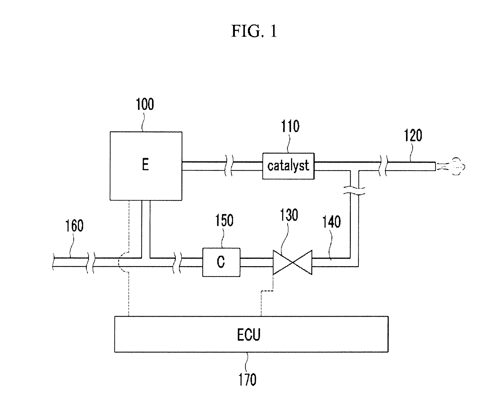
[0024]FIG. 1 is a schematic diagram of an EGR system of an engine according to various embodiments of the present invention.

[0025]Referring to FIG. 1, an EGR system of an engine includes an engine 100, exhaust line 120, a catalyst 110, an intake line 160, an EGR line 140, an EGR valve 130, an EGR cooler 150, and a control portion 170....


PUM


Abstract

An EGR system control method of an engine may include calculating a target mass flux ({dot over (m)}egrd) of EGR gas flowing an EGR line, calculating an effective flowing area (EFA) of an EGR valve disposed on the EGR line, calculating an EGR flow sensitivity by dividing the target mass flux with the effective flowing area, and controlling a real opening rate of the EGR valve by applying the EGR flow sensitivity to a target opening rate of the EGR valve. Accordingly, a gain value is varied on a real time according to an effective flowing area of the EGR valve and a target mass flux of EGR gas such that real opening rate of an EGR valve is accurately and precisely controlled.

Description

CROSS-REFERENCE TO RELATED APPLICATION[0001]This application claims priority to and the benefit of Korean Patent Application No. 10-2010-0123587 filed Dec. 6, 2010, the entire contents of which application is incorporated herein for all purposes by this reference.BACKGROUND OF INVENTION[0002]1. Field of Invention[0003]The present invention relates to an exhaust gas control method of an engine that recirculates exhaust gas of an exhaust line to an intake line and precisely controls a flux of the recirculated exhaust gas.[0004]2. Description of Related Art[0005]Generally, an exhaust gas recirculation system is provided in most diesel engines that are equipped in a vehicle so as to take action with regard to exhaust gas regulations.[0006]The exhaust gas recirculation system returns some of the exhaust gas exhausted from an engine to an intake device of a cylinder to lower combustion temperature of the engine and to decrease NOx thereof.[0007]An EGR valve and an EGR cooler are disposed ...

Claims


Application Information

Patent Timeline
IPC IPC(8): F02M25/07F02D41/26F02D28/00
CPCF02D41/0072Y02T10/47F02D41/18F02D41/0077Y02T10/40
Inventor NAM, KIHOONSUNWOO, MYOUNGHOLEE, MINKWANGPARK, YEONGSEOPOH, BYOUNGGUL
Owner HYUNDAI MOTOR CO LTD
Why Eureka
Try Eureka