Tool Hanger Assembly

Inactive Publication Date: 2012-06-07
KAO JUI CHIEN
View PDF22 Cites 29 Cited by
  • Summary
  • Abstract
  • Description
  • Claims
  • Application Information

AI Technical Summary

Benefits of technology

[0008]The main objective of the present invention is to p

Problems solved by technology

However, the multiple hangers have to be slid into the track one by one, such that assembling the multiple hangers onto the frame is time-consuming, increases assembling cost and is not conveni

Method used


Image

  • Tool Hanger Assembly
  • Tool Hanger Assembly
  • Tool Hanger Assembly

Examples


Example

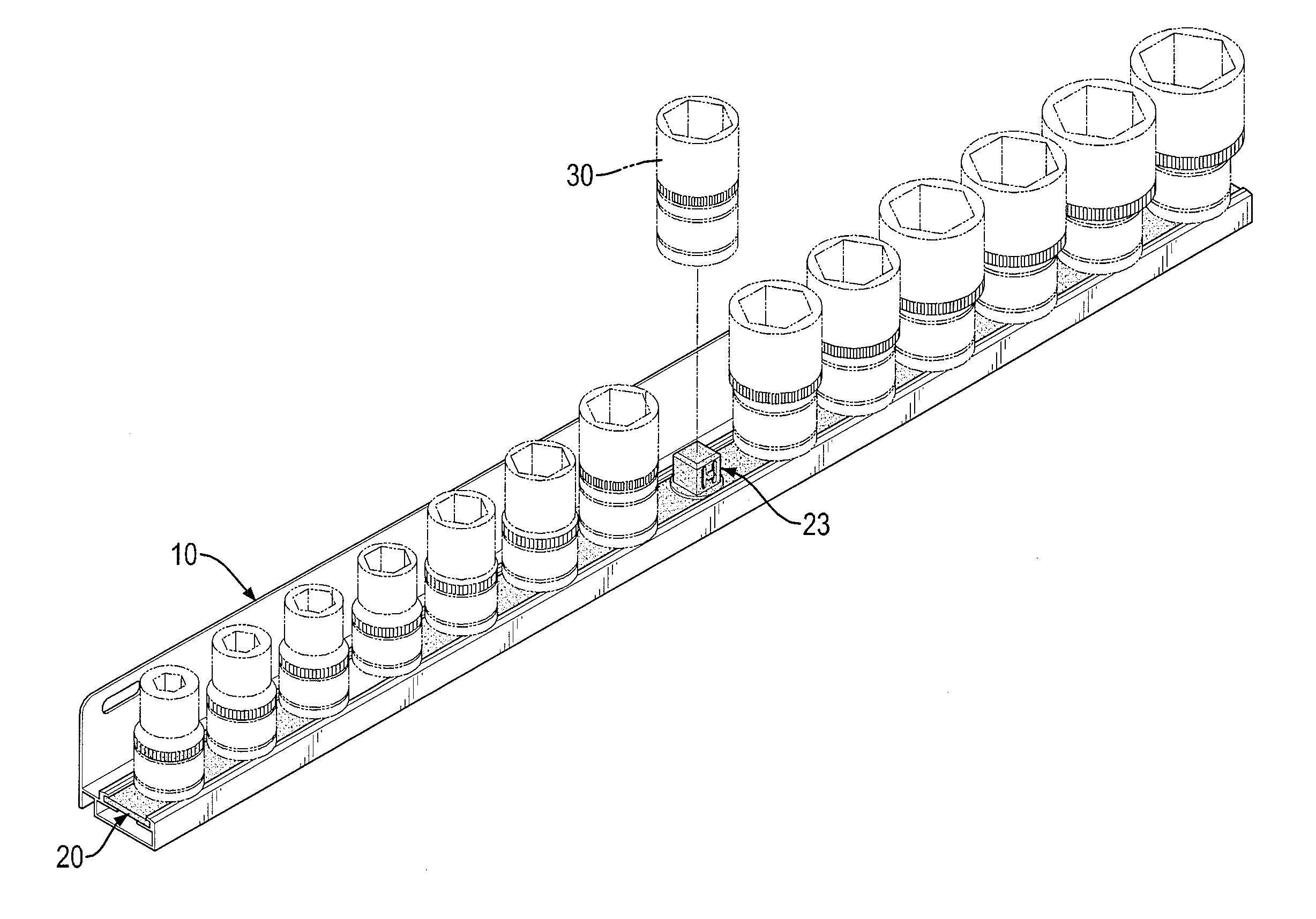
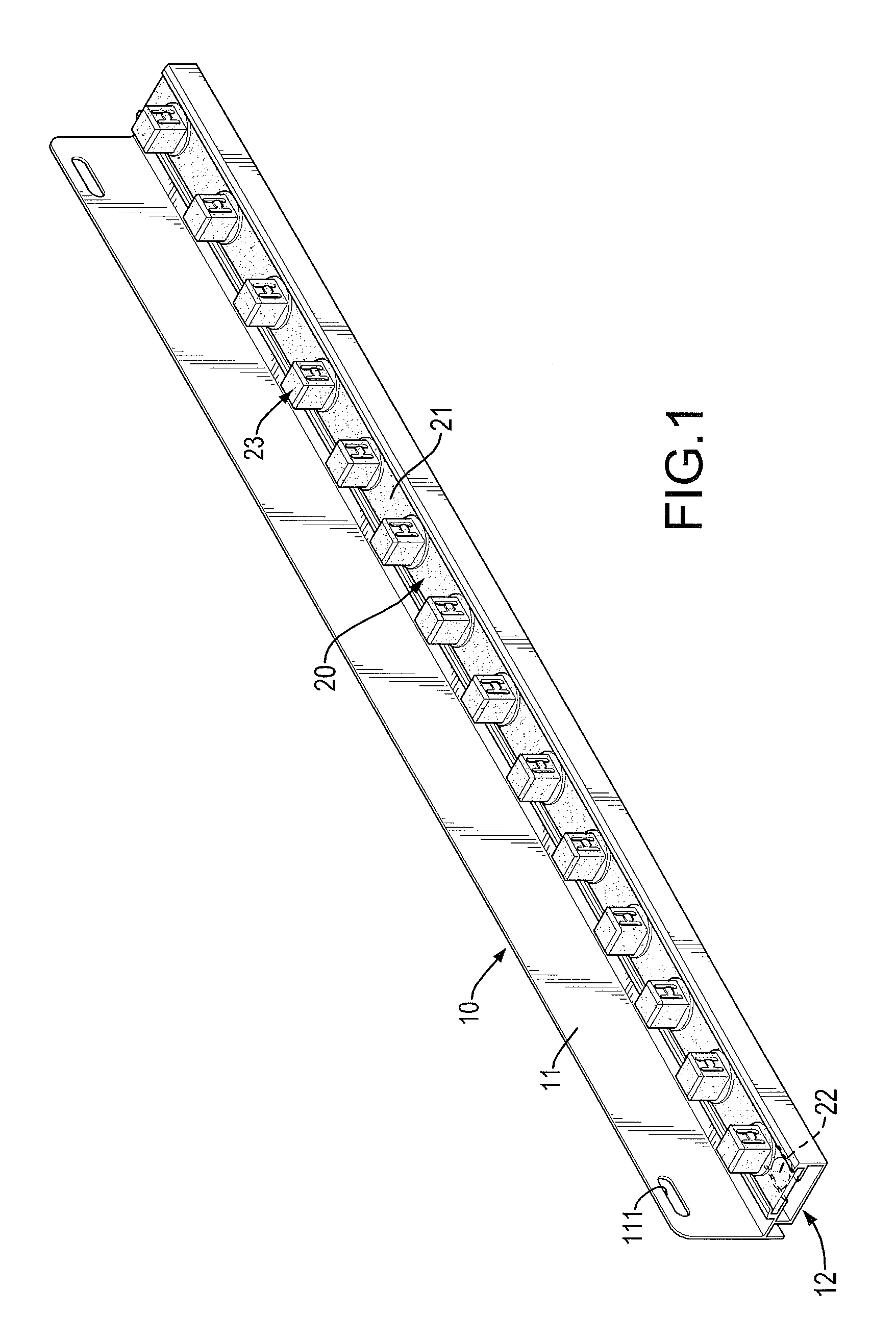
[0021]With reference to FIGS. 1 to 5, a tool hanger assembly in accordance with the present invention comprises a frame 10 and a hanger 20.

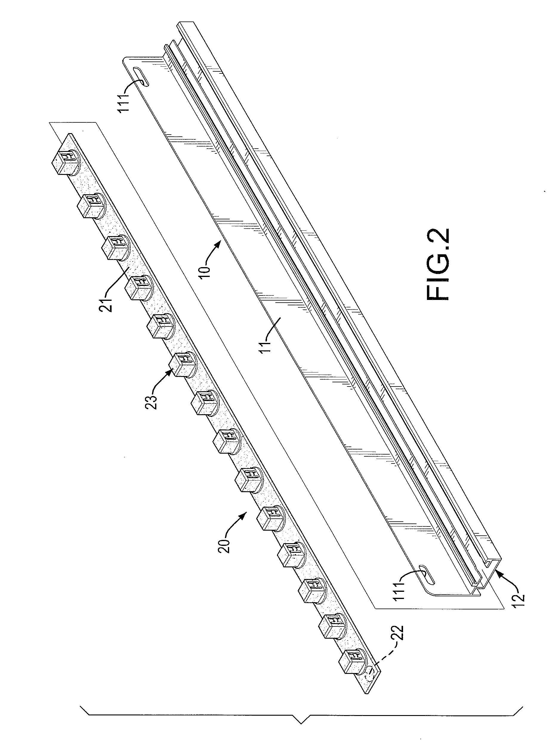
[0022]The frame 10 is made of aluminum and has a back plate 11 and a bracket 12. The back plate 11 is elongated and has a side surface, a top, a bottom, two opposite ends and two mounting holes 111. The bottom of the back plate 11 is opposite to the top of the back plate 11. The mounting holes 111 are formed through near the top and respectively near the opposite ends of the back plate 11.

[0023]The bracket 12 is elongated, is mounted securely on the back plate 11 and has a connecting plate 121, a seat plate 122, a front protrusion 123 and a back protrusion 124. The connecting plate 121 is mounted securely on the side surface near the bottom of the back plate 11 and has a distal portion opposite to the back plate 11.

[0024]The seat plate 122 is mounted securely on the distal portion of the connecting plate 121 and has two opposite ends, a rectangul...


PUM


Abstract

A tool hanger assembly has a frame and a hanger. The frame has a back plate and a bracket. The bracket is mounted securely on the back plate and has a track formed in a top of the bracket. The hanger is mounted securely on the frame and has a base plate and multiple pillars. The base plate is inserted securely in the track. The pillars are securely mounted on the base plate at intervals to allow sleeves to be mounted around. Accordingly, to assemble the hanger having the multiple pillars with the frame is quick, reduces assembling cost and is convenient.

Description

BACKGROUND OF THE INVENTION[0001]1. Field of the Invention[0002]The present invention relates to a tool hanger assembly, and more particularly to a tool hanger assembly to save time for assembling.[0003]2. Description of Related Art[0004]A conventional tool hanger assembly has a frame and multiple hangers. The frame has a track formed in a side surface of the frame. The hangers are slidably mounted in the track and each hanger has a seat protruding from the hanger. Each hanger has a pillar mounted securely on the seat to allow a sleeve to be mounted around.[0005]However, the multiple hangers have to be slid into the track one by one, such that assembling the multiple hangers onto the frame is time-consuming, increases assembling cost and is not convenient.[0006]Additionally, each hanger does not have a flat bottom surface, such that the conventional tool hanger assembly can only be hung on a display board and cannot be positioned on a flat surface.[0007]To overcome the shortcomings,...

Claims


Application Information

Patent Timeline
IPC IPC(8): A47F7/00
CPCB25H3/06
Inventor KAO, JUI-CHIEN
Owner KAO JUI CHIEN
Why Eureka
Try Eureka