Vibrationproof device

a technology of vibrationproof device and cavitation chamber, which is applied in the direction of shock absorber, jet propulsion mounting, machine support, etc., can solve the problems of sudden decrease of pressure localized, noise, and sudden decrease of internal volume of the main liquid chamber, so as to suppress the occurrence of cavitation without reducing the vibrationproof performance or complicating, increase the size of the configuration, and suppress the effect of cavitation immediately

Active Publication Date: 2012-06-07
PROSPIRA CORP
View PDF3 Cites 10 Cited by
  • Summary
  • Abstract
  • Description
  • Claims
  • Application Information

AI Technical Summary

Benefits of technology

[0041]According to the vibrationproof device related to the present invention, occurrence of the cavitation can be suppressed without decreasing the vibrationproof performance or complicating and increasing the size of the configuration. According to the vibrationproof device related to the present invention, the cavitation is immediately suppressed and noise can be decreased even when a large vibration is input in a state where the second liquid is separated from the first liquid.

Problems solved by technology

Meanwhile, in the liquid sealed vibrationproof device, for example, if internal volume of the main liquid chamber is suddenly increased due to rebounding of the elastic body after large vibrations (load) are input due to roughness of a road surface or the like and the internal volume of the main liquid chamber is suddenly decreased, a sudden pressure decrease is locally generated in the vicinity of an opening portion of the main liquid chamber side of the restricting passage.
As a result, there is a problem in that many bubbles are generated in the liquid in the main liquid chamber or the restricting passage and cavitation occurs.
However, shock waves are generated when the bubbles disappear, the shock waves propagate metal materials such as the first mounting member, and noise occurs.

Method used


Image

  • Vibrationproof device
  • Vibrationproof device
  • Vibrationproof device

Examples


first embodiment

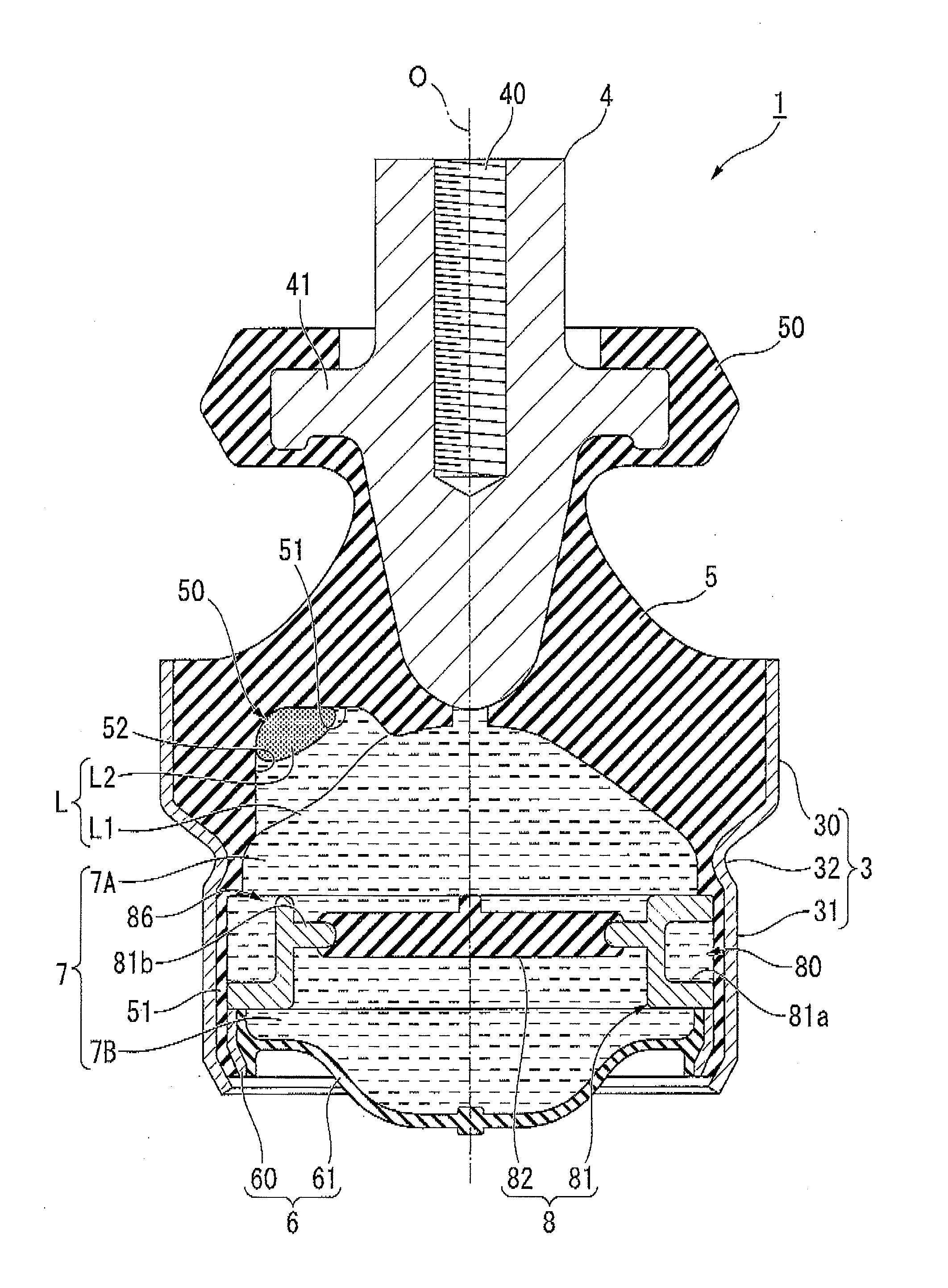
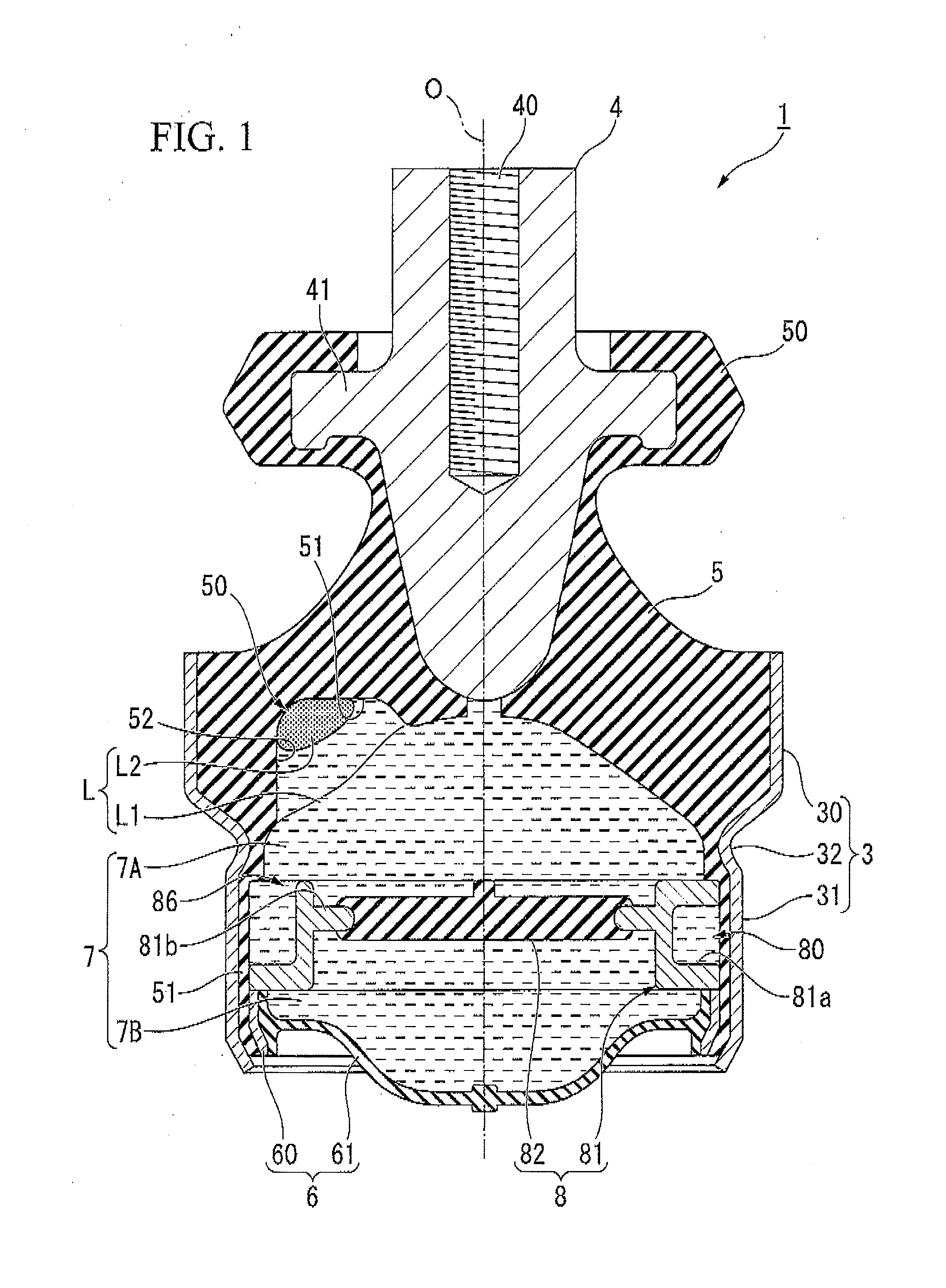
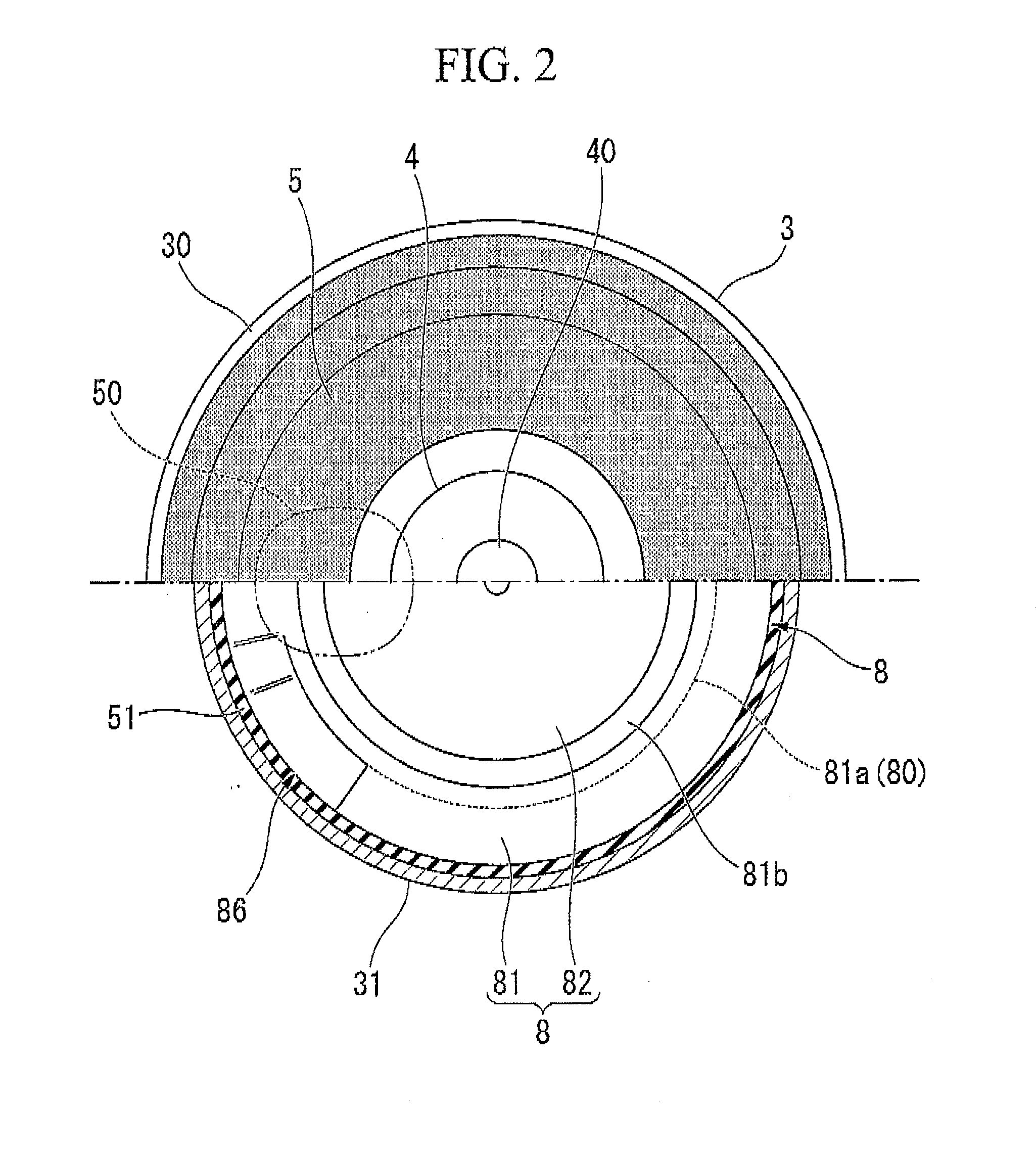
[0048]The vibrationproof device 1 related to the present invention is a device for damping a vibration of a vibration generation portion used when an engine which is an example of the vibration generating portion is mounted on a vehicle body which is an example of a vibration receiving portion. As shown in FIG. 1, the vibrationproof device 1 includes an approximately outer cylinder 3 which is connected to the vehicle body (not shown) through a vehicle body bracket (not shown); an inner cylinder 4 (corresponding to a second mounting member in the present invention) which is connected to an engine (not shown) through an engine bracket (not shown); an elastic body 5 which is elastically connected to the outer cylinder 3 and the inner cylinder 4 and occludes an opening end of the upper side of the outer cylinder 3; a diaphragm 6 which occludes an opening end of the lower side of the outer cylinder 3; and a partition wall 8 which partitions a liquid chamber 7 formed inside the outer cyli...

second embodiment

[0072]The vibrationproof device 101 related to the present invention is a device for damping a vibration of a vibration generation portion used when an engine which is an example of the vibration generating portion is mounted on a vehicle body which is an example of a vibration receiving portion. As shown in FIG. 3, the vibrationproof device 101 includes an approximately cylindrical outer cylinder 103 which is connected to a vehicle body (not shown) through a vehicle body bracket (not shown); an inner cylinder 104 (corresponding to a second mounting member in the present embodiment) which is connected to an engine (not shown) through an engine bracket (not shown); an elastic body 105 which is elastically connected to the outer cylinder 103 and the inner cylinder 104 and occludes an opening end of the lower side of the outer cylinder 103; a diaphragm 106 which occludes an opening end of the upper side of the outer cylinder 103; and a partition wall 108 which partitions a liquid chamb...


PUM


Abstract

A vibrationproof device which is a liquid sealed vibrationproof device includes a tubular first mounting member (3) that is connected to either one of a vibration generating portion and a vibration receiving portion, a second mounting member (4) that is connected to other one, an elastic body (5) that elastically connects the first mounting member (3) and the second mounting member (4), and a partition member (8) that partitions a liquid chamber (7) of the inside of the first mounting member (3) into a main liquid chamber (7A) of an upper side having the elastic body as a portion of a wall surface and an auxiliary liquid chamber (7B) of a lower side, and a restricting passage (80) which communicates with the main liquid chamber (7A) and the auxiliary liquid chamber (7B). In addition, a first liquid (L1) is contained as a main liquid and a second liquid (L2) which is insoluble in the first liquid (L1) is contained as an added liquid in the sealed liquid (L), and the vapor pressure of the second liquid (L2) is higher than the vapor pressure of a main component of the first liquid (L1) in the same temperature and a specific gravity of the second liquid (L2) is lighter than a specific gravity of the first liquid (L1).

Description

FIELD OF THE INVENTION[0001]The present invention relates to a vibrationproof device which is applied to, for example, vehicles or industrial machinery, and absorbs and damps vibration of a vibration generating portion such as an engine. Priority is claimed on Japanese Patent Application No. 2009-139066, filed Jun. 10, 2009 and Japanese Patent Application No. 2009-139068, filed Jun. 10, 2009, the content of which is incorporated herein by reference.DESCRIPTION OF RELATED ART[0002]As the above-described vibrationproof devices, hi the related art, for example, as disclosed in Patent Document 1 below, a configuration is known which includes a tubular first mounting member which is connected to either one of a vibration generating portion and a vibration receiving portion, a second mounting member which is connected to the other one of the vibration generating portion and the vibration receiving portion, an elastic body which elastically connects the first mounting member and the second...

Claims


Application Information

Patent Timeline
Patent Type & Authority Applications(United States)
IPC IPC(8): F16F13/08
CPCF16F13/10B60K5/1208F16F13/107
Inventor MATSUMOTO, YOSHINORIYANAGIDA, MOTOHIROUEKI, AKIRAOHASHI, MASAAKINAGASHIMA, YASUYUKIHIGUCHI, YUTAKA
Owner PROSPIRA CORP
Why Eureka
Try Eureka