Current Driver, Electronic Device and Current Driving Method
- Summary
- Abstract
- Description
- Claims
- Application Information
AI Technical Summary
Benefits of technology
Problems solved by technology
Method used
Image
Examples
Embodiment Construction
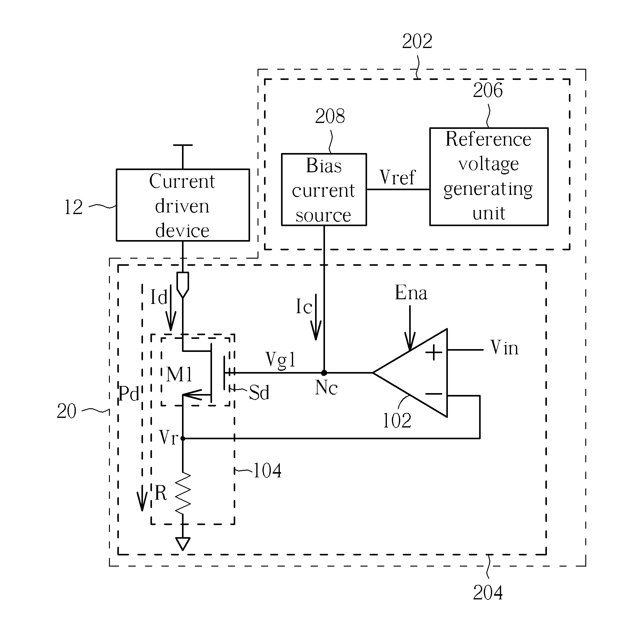
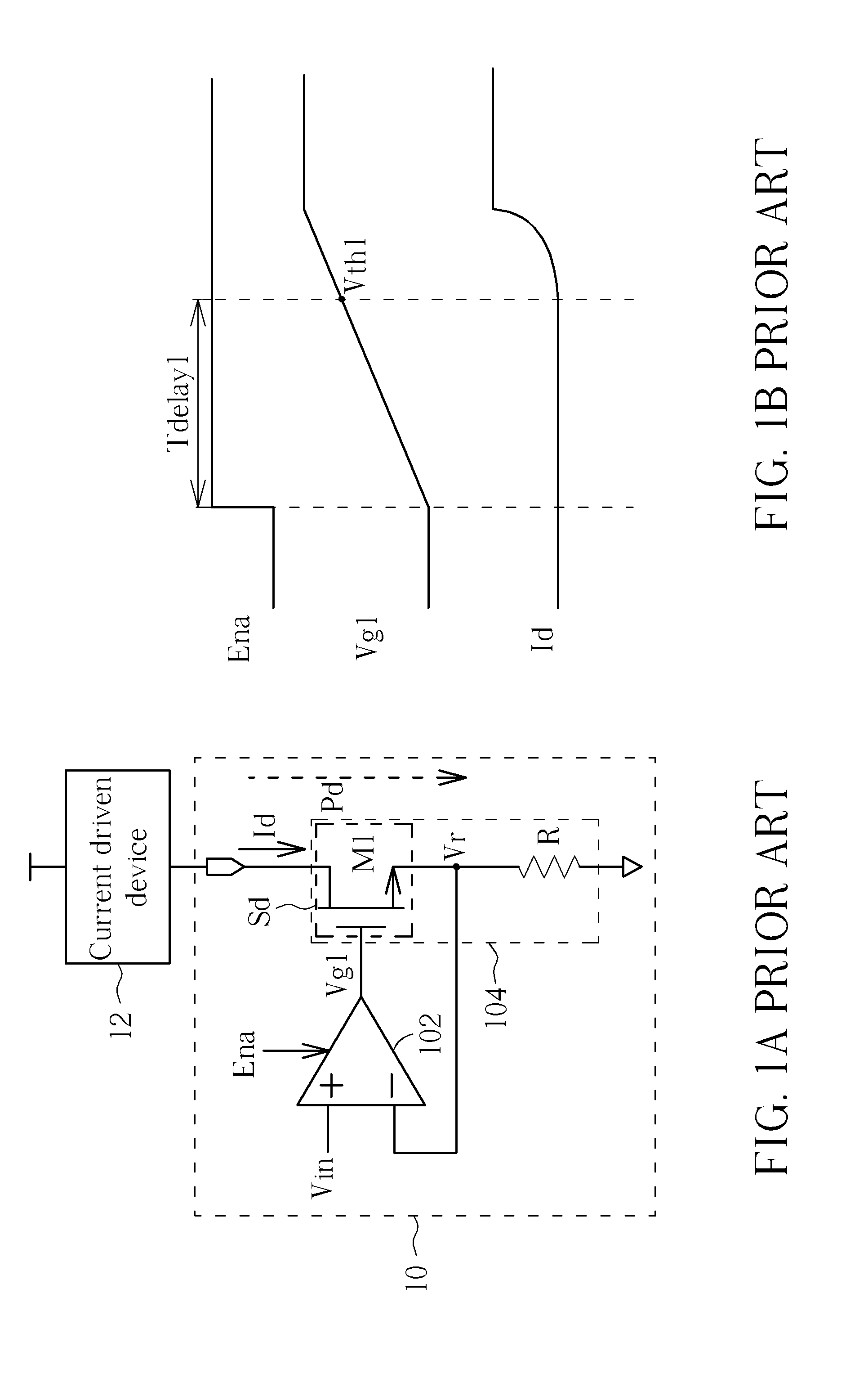
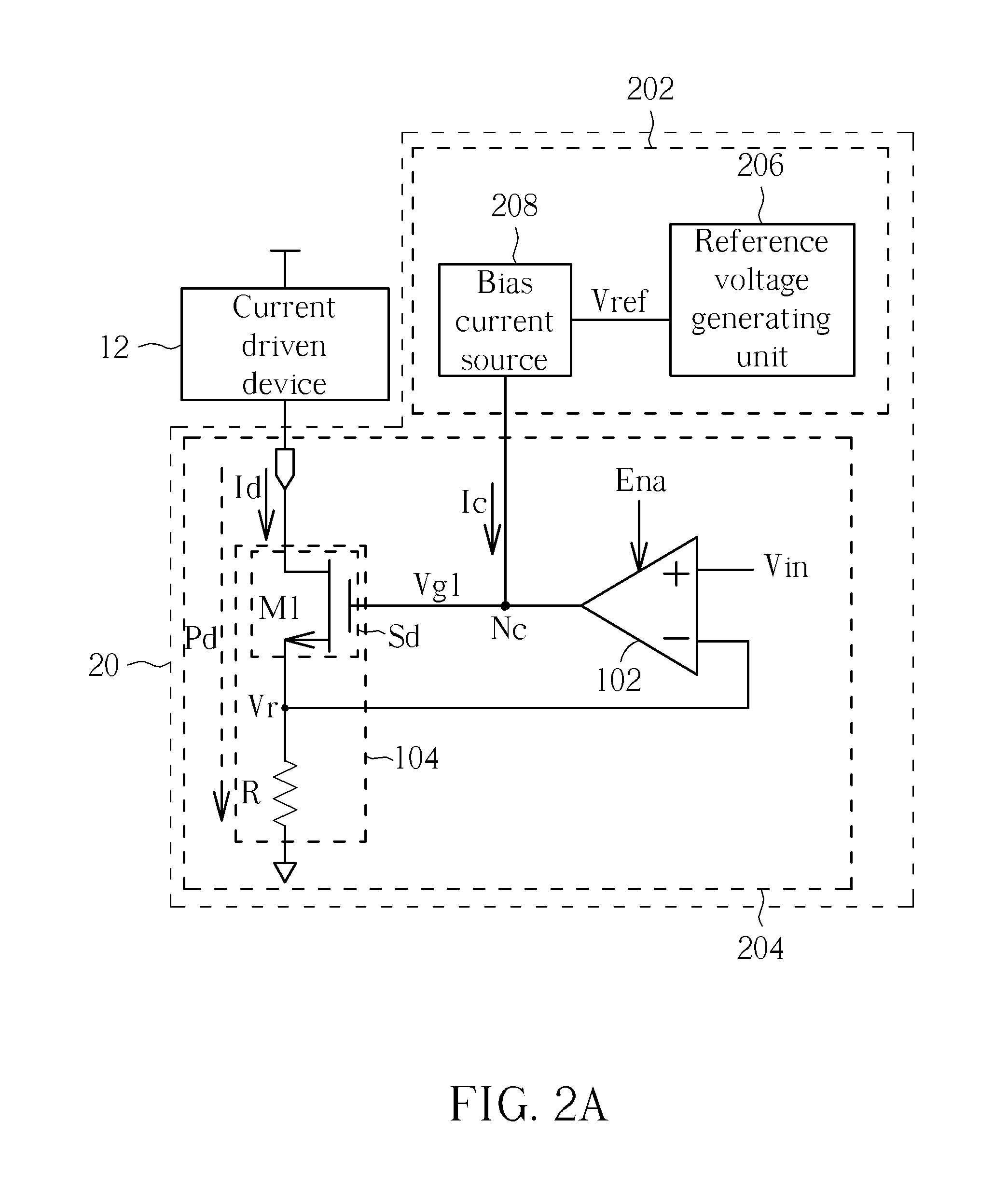
[0026]Please refer to FIG. 2A, which is a block structure diagram of a current driver 20 according to an embodiment. The current driver 20 includes a driving circuit 204 and an accelerating circuit 202. The driving circuit 204 is configured to generate a driving current Id to drive a current driven device 12. Detailed structures and operations of the driving circuit 204, for example, can be configured to be similar to those of the current driver 10 shown in FIG. 1, including the buffer amplifier 102 and the bias current source 104. Additionally, the driving circuit 204 and the current driven device 12 can be disposed in any electronic device.
[0027]On the other hand, a main difference between the current driver 10 and 20 is that the current driver 20 further includes the accelerating circuit 202. During an activation period of the driving circuit 204, the accelerating circuit 202 can be simultaneously activated to provide an accelerating current Ic flowing through a driving control n...
PUM
 Abstract
Description
Claims
Application Information
 - R&D Engineer
- R&D Manager
- IP Professional
- Industry Leading Data Capabilities
- Powerful AI technology
- Patent DNA Extraction
Browse by: Latest US Patents, China's latest patents, Technical Efficacy Thesaurus, Application Domain, Technology Topic, Popular Technical Reports.
© 2024 PatSnap. All rights reserved.Legal|Privacy policy|Modern Slavery Act Transparency Statement|Sitemap|About US| Contact US: help@patsnap.com


