Speckle reduction for laser projection displays

a laser projection display and speck reduction technology, applied in semiconductor lasers, instruments, optical elements, etc., can solve the problems of increasing the complexity, size and cost of the display system, and the need to address the problem of laser speckling, so as to reduce the noise of speckling

Active Publication Date: 2012-06-07
MAXIM INTEGRATED PROD INC
View PDF7 Cites 26 Cited by
  • Summary
  • Abstract
  • Description
  • Claims
  • Application Information

AI Technical Summary

Benefits of technology

[0011]Various embodiments of the present invention relate to laser driving systems, devices and methods of ap

Problems solved by technology

However, to realize a laser illumination system, laser speckling is an issue that needs to be addressed.
The optical interference of the light shows up as speckles in the image received by the audience.
However, all these methods involve adding more components to the optical

Method used


Image

  • Speckle reduction for laser projection displays
  • Speckle reduction for laser projection displays
  • Speckle reduction for laser projection displays

Examples


Embodiment Construction

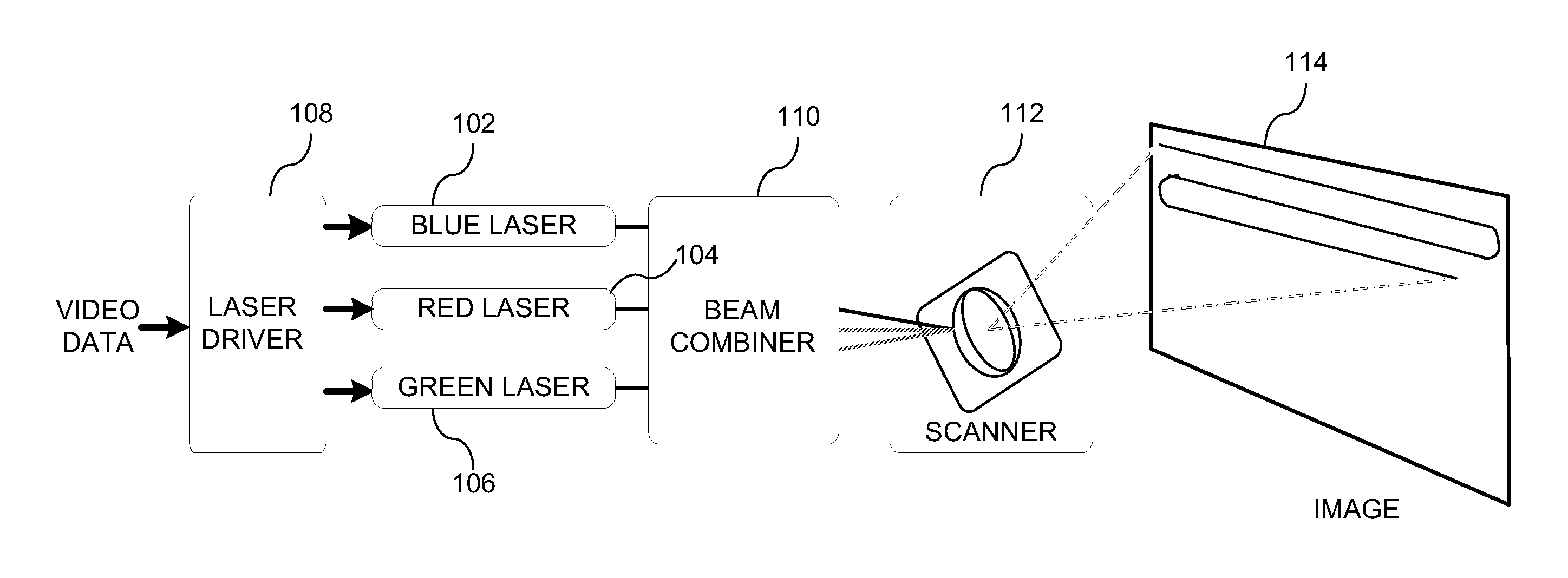
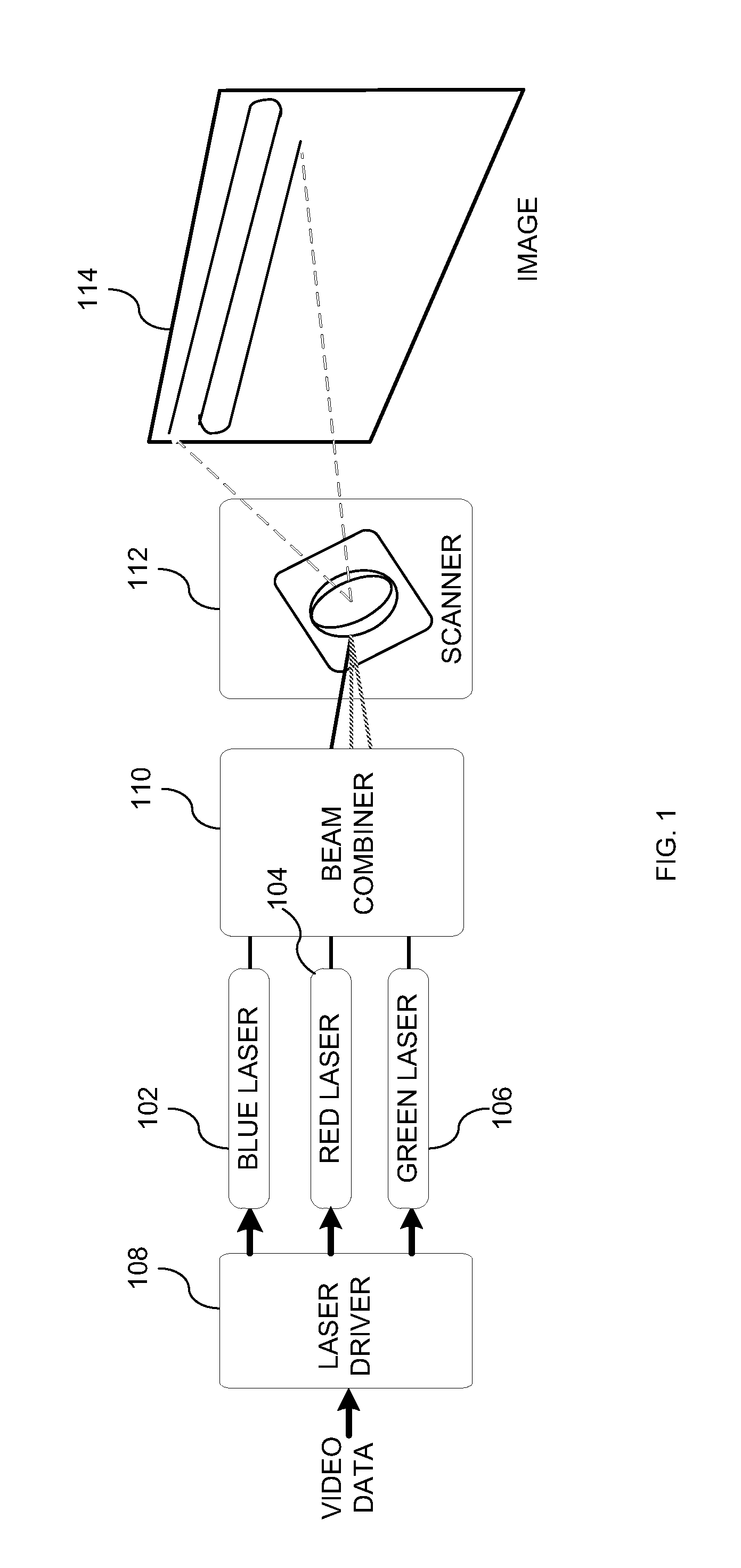
[0023]Embodiments of the present invention provide systems, devices and methods of employing pulsed drive currents to drive the lasers and reduce the speckling noise on the projected images in a laser-based projection display. In particular, short light-off pulses are introduced into the modulation current driving the laser instead of using RF modulation. In the following description, for purposes of explanation, specific details are set forth in order to provide an understanding of the invention. It will be apparent, however, to one skilled in the art that the invention can be practiced without these details. One skilled in the art will recognize that embodiments of the present invention, described below, may be performed in a variety of ways and using a variety of structures. Those skilled in the art will also recognize additional modifications, applications, and embodiments are within the scope thereof, as are additional fields in which the invention may provide utility. Accordin...


PUM


Abstract

Various embodiments of the present invention relate to a laser driver, and more particularly, to systems, devices and methods of applying low current pulses to a laser modulation current to reduce the speckling noise on the projected images.

Description

CROSS REFERENCE TO RELATED PATENT APPLICATIONS[0001]This application claims priority to U.S. Provisional Application Ser. No. 61 / 420,212, entitled “Speckle Reduction for Laser Projection Displays,” filed Dec. 6, 2010, which application is incorporated herein by reference in its entirety.BACKGROUND[0002]A. Technical Field[0003]The present invention relates to the field of laser illumination systems, and more particularly, to systems, devices and methods of employing pulsed drive currents to drive the lasers and reduce the speckling noises on the projected images.[0004]B. Background of the Invention[0005]Laser light sources used for projection display have shown advantages compared with the conventional light sources, such as ultra-high pressure (UHP) lamps, high-intensity discharge (HID) lamp and xenon lamps. The laser light sources provide wide color expression with narrow spectrum. The color gamut of a light source based on red, green and blue (RGB) lasers can be easily expanded be...

Claims


Application Information

Patent Timeline
IPC IPC(8): H01S3/13
CPCG02B27/48H04N9/3129H01S5/06216H01S5/0428
Inventor QUIRK, JOHNLYON, CRAIG
Owner MAXIM INTEGRATED PROD INC
Why Eureka
Try Eureka