X-ray diffraction apparatus and x-ray diffraction measurement method

a technology of x-ray diffraction and measurement method, applied in the direction of material analysis using radiation diffraction, instruments, measurement devices, etc., can solve the problems of inability to apply methods to optically transparent substances, difficult rocking curve analysis, time-consuming operations, etc., and achieve the effect of performing both quickly and accurately

Active Publication Date: 2012-06-07
RIGAKU CORP
View PDF2 Cites 13 Cited by
  • Summary
  • Abstract
  • Description
  • Claims
  • Application Information

AI Technical Summary

Benefits of technology

[0036]According to the X-ray diffraction apparatus of the present invention, a transparent sample that cannot be made visible with an optical image-capturing means such as an optical microscope or the like can be made visible by an X-ray topography means and made into a measurement object. Additionally, an arbitrary position in an in-plane region of a sample that has been made visible can be clearly specified by a video synthesis means. The specified positional information can be adapted as data for a diverse range of X-ray measurements subsequently performed on the sample.
[0037]In conventional X-ray diffraction apparatuses, the position in which an X-ray is incident on a sample had to be aligned with the region of interest by trial and error in a case in which the region of interest in an X-ray topograph was to be set and an X-ray measurement performed. By contrast, according to the present invention, the subsequently performed X-ray measurement can be performed both quickly and accurately because the region of interest in an X-ray topograph can be clearly specified in a short timespan by the video synthesis means.
[0038]According to the X-ray diffraction measurement method of the present invention, a transparent substance can be made visible by an X-ray topograph, and X-ray measurement can be performed once the arbitrary position of interest in the in-plane region of the X-ray topograph has been clearly set by coordinates or the like.

Problems solved by technology

However, the position of the section where rocking curve measurements is to be performed has to be defined by methods that take time and are imprecise.
For this reason, operations whereby a section having crystal defects determined by X-ray topography is set as a section to be measured using rocking curve analysis are extremely difficult and time-consuming operations.
The methods using a reflective optical microscope have a problem, however, in that, while effective in cases in which the measurement object is an optically opaque substance, these methods cannot be applied to optically transparent substances.

Method used


Image

  • X-ray diffraction apparatus and x-ray diffraction measurement method
  • X-ray diffraction apparatus and x-ray diffraction measurement method
  • X-ray diffraction apparatus and x-ray diffraction measurement method

Examples


Embodiment Construction

[0043]The following is an explanation, made on the basis of an embodiment, of the X-ray diffraction apparatus and the X-ray diffraction measurement method relating to the present invention. It is apparent that the present invention is not restricted to the embodiment. The explanation from here on refers to the drawings, but the drawings sometimes show constituent components at a scale that is different from the actual proportions in order to make feature-specific sections easier to understand.

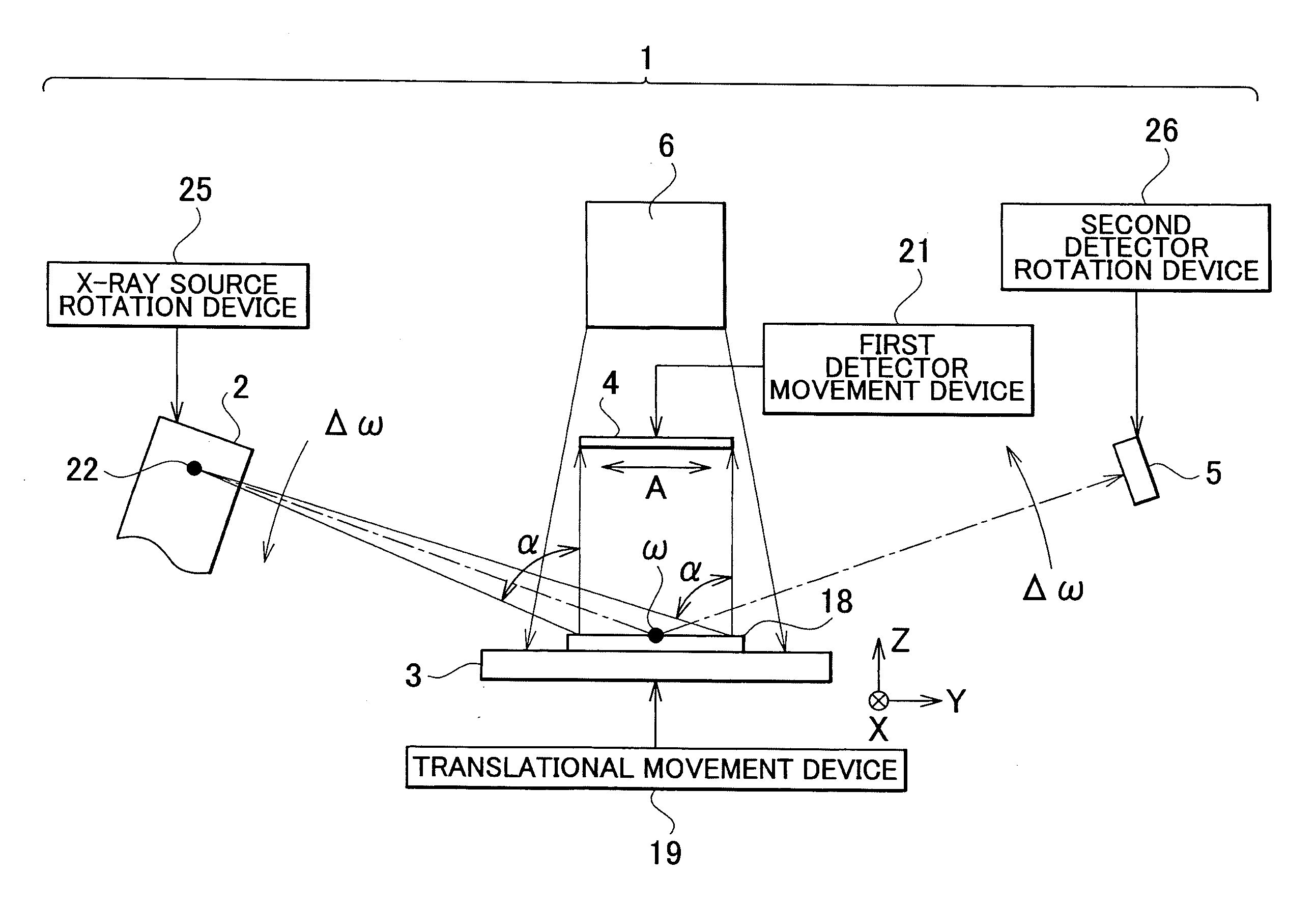
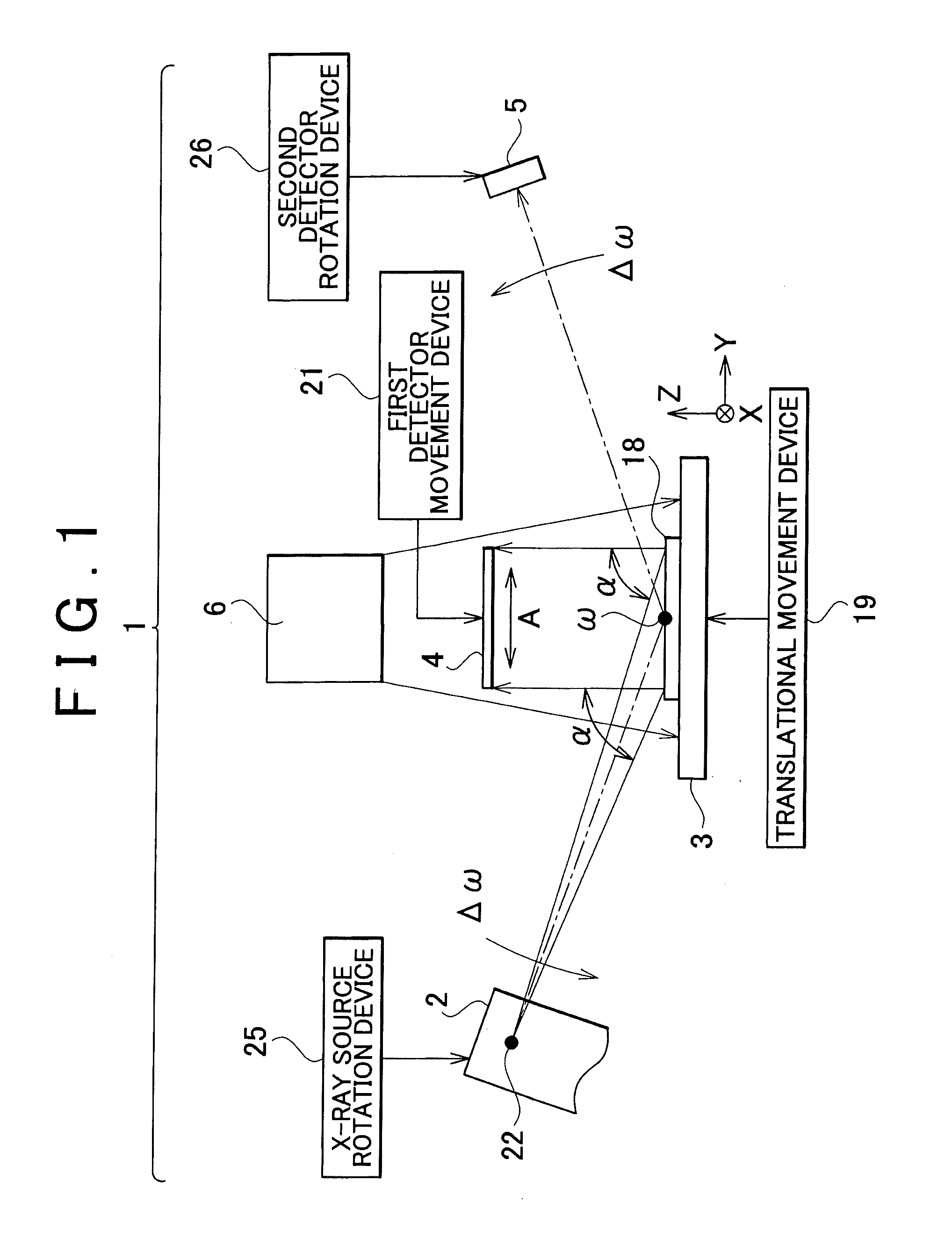
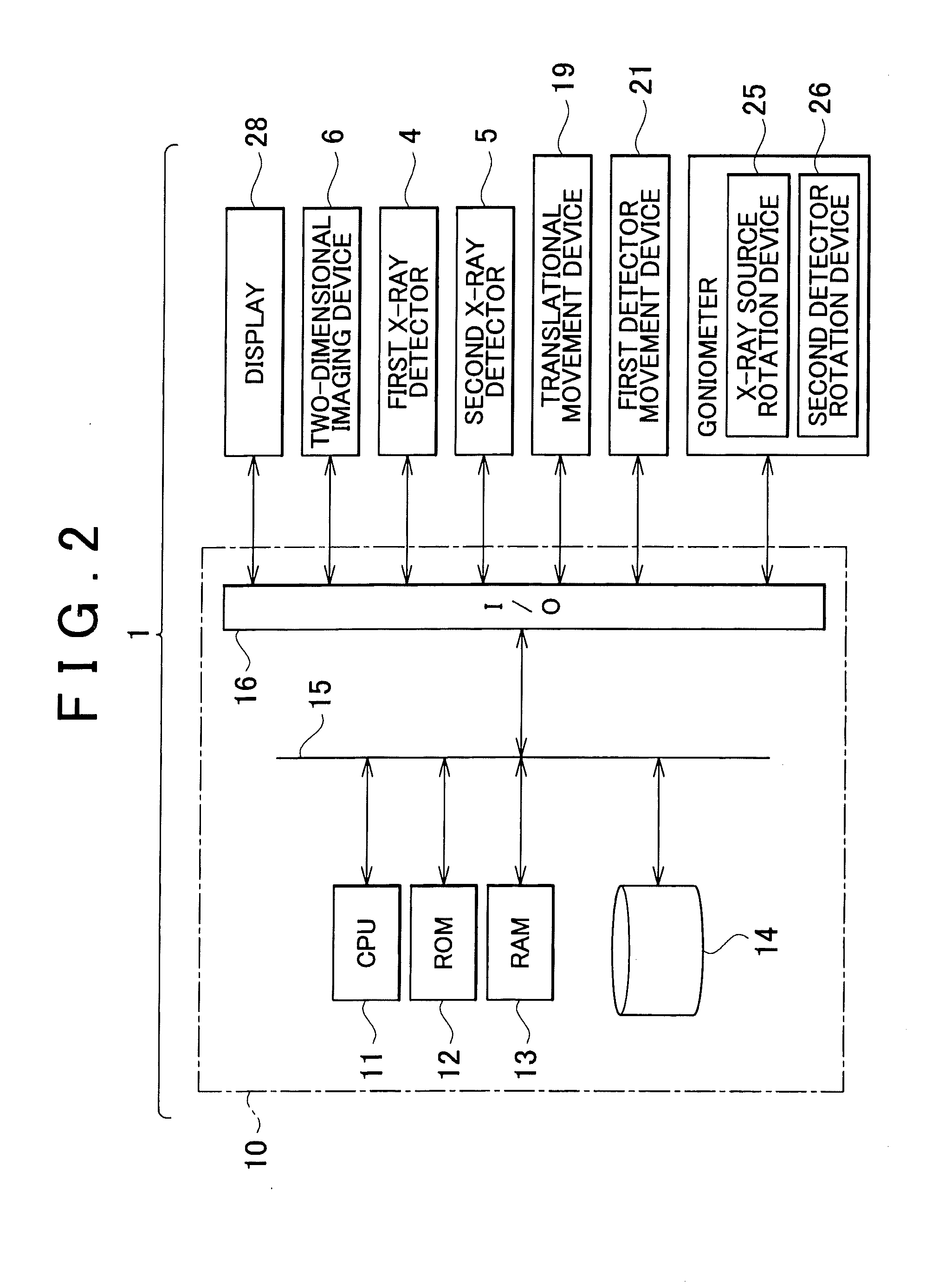
[0044]FIG. 1 shows a mechanical section of an embodiment of the X-ray diffraction apparatus relating to the present invention. FIG. 2 shows an electric control panel of the present embodiment. In FIG. 1, an X-ray diffraction apparatus 1 has an X-ray tube 2, a sample mount 3, a first X-ray detector 4, a second X-ray detector 5, and a two-dimensional imaging device 6, which is an optical image-capturing means. In FIG. 2, the X-ray diffraction apparatus 1 has a control device 10. The control devic...


PUM

PropertyMeasurementUnit
optical image-aaaaaaaaaa
transparentaaaaaaaaaa
reciprocal lattice mappingaaaaaaaaaa

Abstract

There is provided an X-ray diffraction apparatus comprising an X-ray topography device for providing a spatial geometric correspondence to an X-ray exiting from a planar region of a sample to detect the X-ray as a planar X-ray topograph, and outputting the X-ray topograph as a signal; a two-dimensional imaging device for receiving a light-image of the planar region of the sample and outputting the light-image as a signal specified by planar positional information; and a video-synthesizing arithmetic control device for generating synthesized video data on the basis of an output signal from the X-ray topograph and an output signal from the imaging device.

Description

BACKGROUND OF THE INVENTION[0001]1. Field of the Invention[0002]The present invention relates to an X-ray diffraction apparatus and X-ray diffraction measurement method based on X-ray topography.[0003]2. Description of the Related Art[0004]X-ray topography has been known as one of X-ray diffraction measurement methods. X-ray topography is a measurement method devised so that a wide area of a sample is irradiated with X-rays, and the diffracted rays exiting the sample are detected in a plane (that is, in two dimensions) by an X-ray detector. Specifically, X-ray topography is a method in which diffracted rays that have exited from a planar region of a sample are provided with a spatial geometric correspondence and captured as a planar X-ray diffraction image. The planar X-ray diffraction image is called an X-ray topograph.[0005]The form characteristics that appear in an X-ray topograph typically represent the compositional characteristics of an object. For example, lattice defects and...

Claims


Application Information

Patent Timeline
Patent Type & Authority Applications(United States)
IPC IPC(8): G01N23/207G01N23/20
CPCG01N23/207
Inventor OZAWA, TETSUYAMATSUO, RYUJIINABA, KATSUHIKO
Owner RIGAKU CORP
Why Eureka
Try Eureka