Support structure for a wind turbine and procedure to erect the support structure

a technology for supporting structures and wind turbines, which is applied in the direction of mechanical equipment, building repairs, machines/engines, etc., can solve the problems of high cost of assembly of towers, inability to deal with, in a cost-effective manner, against the cost-effectiveness of the project, etc., and achieve the effect of reducing the cost of assembly and reducing the cost of construction

Inactive Publication Date: 2012-06-07
PACADAR
View PDF12 Cites 31 Cited by
  • Summary
  • Abstract
  • Description
  • Claims
  • Application Information

AI Technical Summary

Benefits of technology

[0058]As previously mentioned, the invention also proposes a system for connecting prefabricated pre-tensioned elements based on its own prestressing cables, which offers the possibility for connection between prefabricated elements with pre-tensioned reinforcement without the need for additional elements based on the subsequent tensioning of part of the tensioning cables of the wall piece.
[0059]For such purpose, the prestressing cables use

Problems solved by technology

An extrapolation of towers today (up to 70 m in height) built by means of curved and electrowelded plates, transversely attached by means of flanges, does not allow dealing with, in a cost-effective manner, the new features required of said elements, especially due to the enormous flexibility of this type of structures made of steel and to the incompatibility of this characteristic with the requirements extracted from the dynamic calculation of these new towers.
In addition to being expensive, these solutions have the problem of the long periods required for performing them, which works directly against the cost-effectiveness of the project.
In thi

Method used


Image

  • Support structure for a wind turbine and procedure to erect the support structure
  • Support structure for a wind turbine and procedure to erect the support structure
  • Support structure for a wind turbine and procedure to erect the support structure

Examples


Embodiment Construction

[0094]In view of the discussed figures and in accordance with the number used, an embodiment of the invention comprising the parts described below can be seen in said figures.

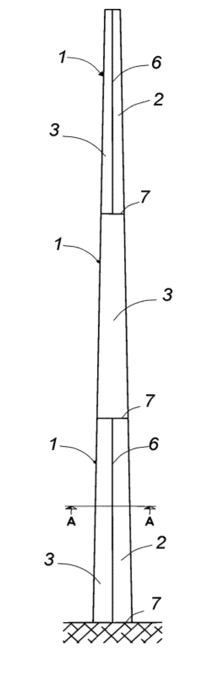
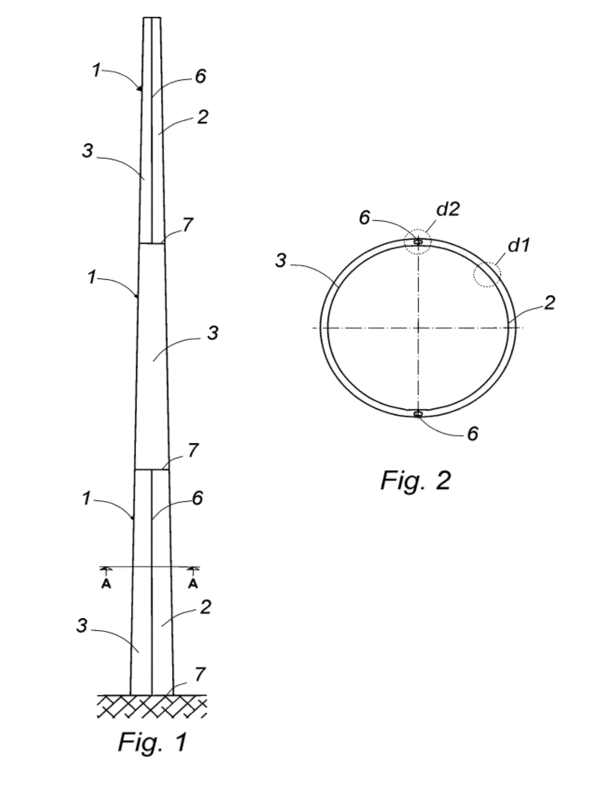
[0095]Thus, as depicted in FIGS. 1 and 2, the support structure for wind turbines generating electric energy and for other uses made of entirely prefabricated prestressed concrete is formed by a prefabricated column shaft -1- made of high-strength concrete which is prestressed or post-tensioned in the manufacturing bed which can self-compacting, if necessary, having a frustoconical shape with variable height made by means of at least two pieces -2- and -3- with semicircular or polygonal section (not illustrated), a thin wall of 5 to 30 cm having a centered prestressing -4- and a non-prestressed reinforcement in the perimeter of the section -5- as is observed in detail “d1” depicted in FIG. 6 and attached to each other by means of longitudinal joints -6-.

[0096]The prestressing -4- can have slight variations with...


PUM


Abstract

The invention comprises a series of spans of column shaft (1) with a frustoconical shape, each span integrating two or more parts (2) and (3) with a polygonal or circular section formed with pieces prestressed in a bed in the factory, with centered or slightly deviated prestressing (4) and non-prestressed reinforcement (5) in the perimeter of the section or fibers, attached by means of wet or dry longitudinal joints (6), rotated in plan view or not, and transverse joints (7) which can be at different levels and provide continuity or not to the general prestressing, for a joining by means of steel bars (12), and in the case of the attachment to the foundation with direct positioning of the starter bars at the time said foundation is built, or by means of jacket tubes which will subsequently receive the mentioned bars (16).

Description

[0001]The present invention relates to a vertical support structure or tower for wind turbines generating electric energy or other uses, made of prestressed concrete, providing a frustoconical or cylindrical column shaft of prestressed concrete with variable height built by means of annular sectors, each of which comprises several wall pieces with a semicircular or polygonal section or semicircular or polygonal sectors, longitudinally attached to each other, and in the case of several superimposed in height, longitudinally attached with a system allowing the structural continuity of the tower. Either the wind turbine directly or another metal column shaft on which the turbine will finally be fixed will be located at its upper end.[0002]This invention also has its application in the field of construction in general and especially in the industry for building and installing support structures for wind turbines generating electric energy.[0003]A second aspect of the invention relates t...

Claims


Application Information

Patent Timeline
IPC IPC(8): F03D11/04E04H12/12
CPCE04H12/085E04H12/16F03D1/001F03D11/045Y02E10/728E04H12/12F03D11/04F03D13/22F03D13/20F03D13/10Y02E10/72
Inventor MARTINEZ DE CASTANEDA, FRANCISCO JAVIERCIDONCHA ESCOBAR, MANUEL
Owner PACADAR
Why Eureka
Try Eureka