Radio communication system, small cell base station, radio terminal, transmission power control method, and allocation control method

a radio communication system and small cell technology, applied in the direction of power management, wireless commuication services, network topologies, etc., can solve the problems of propagation loss, low throughput of the radio terminal connected to interference of the large cell base station, so as to reduce interference

Active Publication Date: 2012-06-07
KYOCERA CORP
View PDF2 Cites 32 Cited by
  • Summary
  • Abstract
  • Description
  • Claims
  • Application Information

AI Technical Summary

Benefits of technology

[0034]According to the features of the present invention, it is possible to provide a radio communication system, a small cell base station, a radio terminal, a transmission power control method, and an allocation control method, by which it is possible to reduce interference to a large cell base station from a radio terminal connected to a small cell base station.

Problems solved by technology

In such a case, when a radio terminal connected to the small cell base station and a radio terminal connected to the large cell base station use the same frequency band in order to perform communication, the large cell base station is affected by interference due to a radio signal transmitted to the small cell base station from the radio terminal connected to the small cell base station.
Specifically, when propagation loss between the large cell base station and the radio terminal connected to the small cell base station is small, the large cell base station is affected by large interference from the radio terminal connected to the small cell base station, resulting in a problem that the throughput of the radio terminal connected to the large cell base station is lowered.
In addition, the “propagation loss” includes distance attenuation, shadowing loss, and feature pass loss.

Method used


Image

  • Radio communication system, small cell base station, radio terminal, transmission power control method, and allocation control method
  • Radio communication system, small cell base station, radio terminal, transmission power control method, and allocation control method
  • Radio communication system, small cell base station, radio terminal, transmission power control method, and allocation control method

Examples


first embodiment

(1) First Embodiment

[0052]A first embodiment will be described in sequence of (1.1) Configuration of radio communication system, (1.2) Details of transmission power method, (1.3) Operation of radio communication system, and (1.4) Effect of first embodiment.

[0053](1.1) Configuration of Radio Communication System

[0054](1.1.1) Entire Schematic Configuration

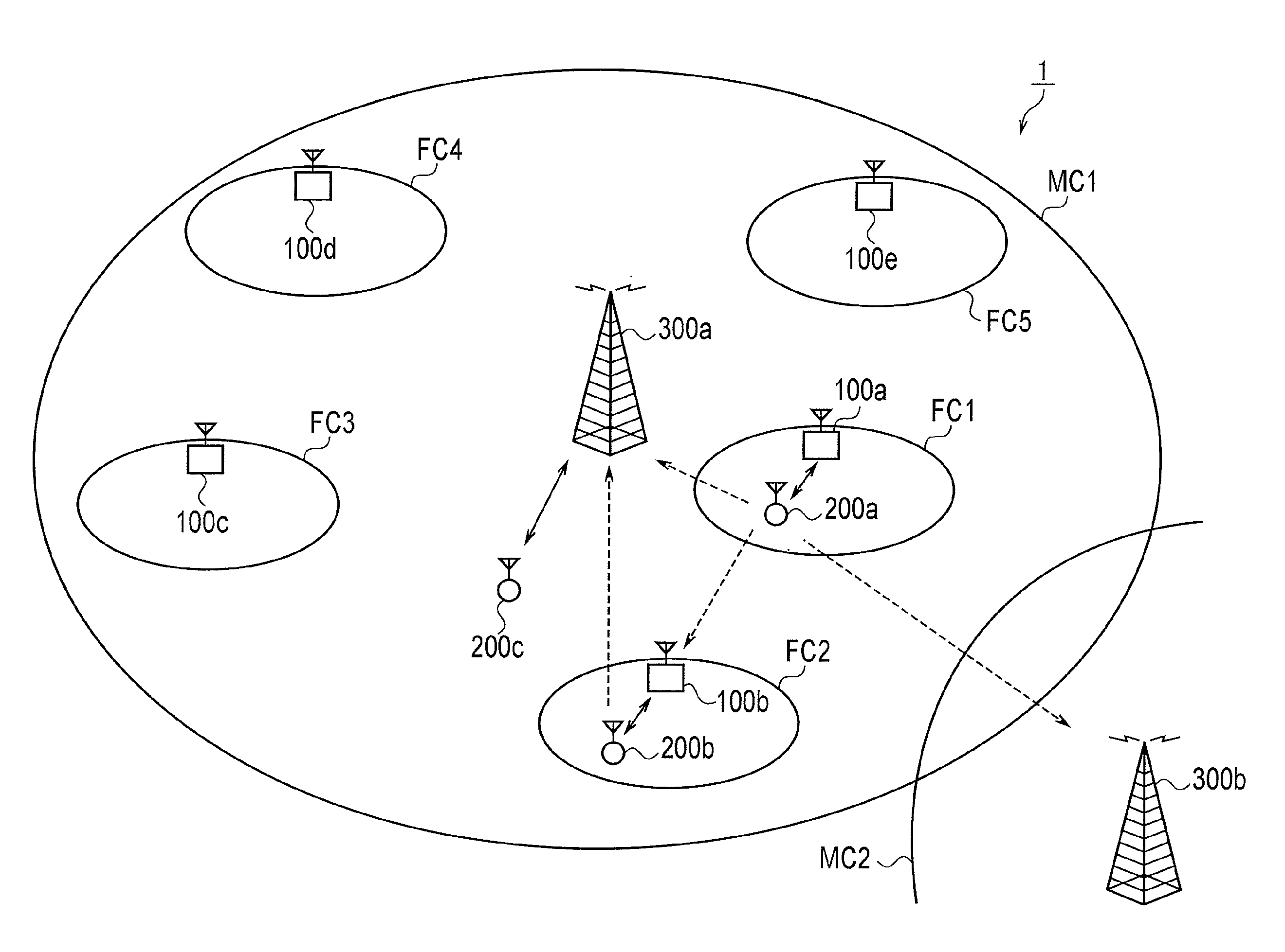
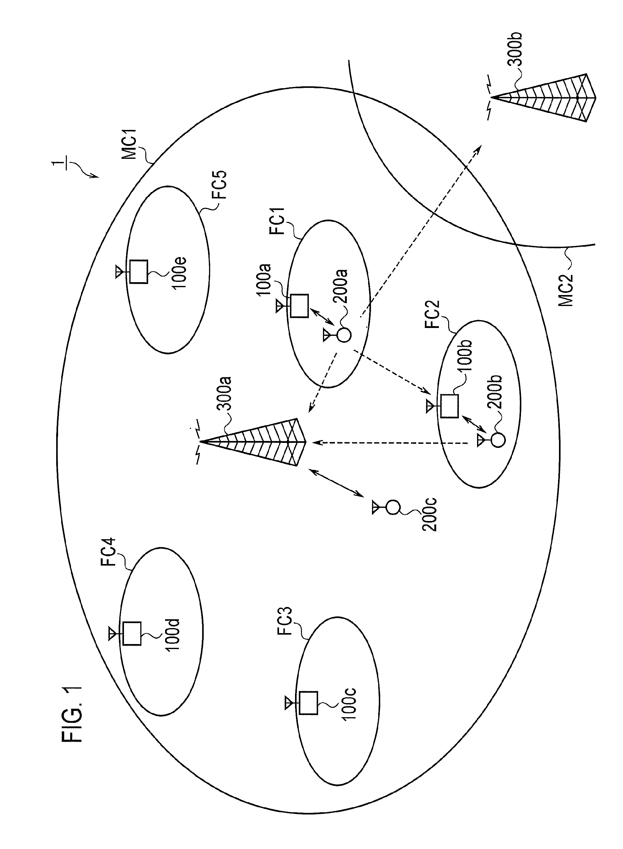
[0055]FIG. 1 is a schematic configuration diagram of a radio communication system 1 according to the first embodiment. The radio communication system 1, for example, has a configuration based on the LTE-Advanced positioned as the 4th-generation (4G) cellular telephone system.

[0056]As illustrated in FIG. 1, the radio communication system 1 includes macro cell base stations (large cell base stations) 300a and 300b, which respectively form macro cells (large cells) MC1 and MC2, and femto cell base stations (small cell base stations) 100a to 100e which respectively form femto cells (small cells) FC1 to FC5. The macro cells MC1 and MC2, f...

second embodiment

(2) Second Embodiment

[0127]In a second embodiment, it is assumed that the OI or information (hereinafter, referred to as “OI information”) similar to the OI is transmitted from the macro cell base station 300 to the femto cell base station 100, and the femto cell base station 100 adaptively selects an appropriate function Poffset (x) for adjustment from candidates of a plurality of functions Poffset (x) for adjustment prepared in advance according to the received OI information.

[0128]FIG. 6 is a sequence diagram illustrating an operation example of the radio communication system 1 according to the second embodiment of the present invention. A description about an operation the same as the first embodiment will be omitted in order to avoid redundancy.

[0129]In step S201, the macro cell base station 300a transmits OI information, which is related to the level of interference to the macro cell base station 300a from the radio terminal 200a, to the femto cell base station 100a through co...

third embodiment

(3) Third Embodiment

[0137]In the above-mentioned first and second embodiments, the execution of the uplink transmission power control is lead by the femto cell base station 100. However, in a third embodiment, the execution of the uplink transmission power control is lead by the radio terminal 200.

[0138]For example, for the transmission power control of the radio terminal 200a connected to the femto cell base station 100a, the radio terminal 200a calculates propagation loss by a reference signal transmitted from the femto cell base station 100a and the macro cell base station 300a, and determines increase or decrease in the transmission power using the calculated propagation loss, thereby performing the transmission power control.

[0139](3.1) Configuration of Radio Terminal

[0140]Next, the configuration of the radio terminal 200a according to the third embodiment will be described. Another radio terminal 200 has the same configuration as that of the radio terminal 200a. FIG. 8 is a bl...


PUM


Abstract

A radio communication system wherein a femto cell base station (100a) is located in a macro cell (MC1) and a radio terminal (200a) is connected to the femto cell base station (100a) and wherein the femto cell base station (100a) or radio terminal (200a) controls, based on a propagation loss between the radio terminal (200a) and a macro cell base station (300a) existing in the neighborhood of the radio terminal (200a), the transmission power of a radio signal to be transmitted from the radio terminal (200a) to the femto cell base station (100a).

Description

TECHNICAL FIELD[0001]The present invention relates to a radio communication system, a small cell base station, a radio terminal, and a transmission power control method, which control the transmission power of a radio signal transmitted from a radio terminal.[0002]Furthermore, the present invention relates to a small cell base station and an allocation control method, which control the allocation of a radio resource to a radio terminal.BACKGROUND ART[0003]As the next-generation radio communication system for performing a higher speed communication with a higher capacity, as compared with the 3rd-generation and 3.5th-generation radio communication systems operated at present, LTE has been standardized in 3GPP which is the standardization body of a radio communication system. The technical specifications of the LTE have been specified as 3GPP Release 8, and Release 9, which is an upgrade version of Release 8, and LTE Advanced, which is a sophisticated version of the LTE, have been cur...

Claims


Application Information

Patent Timeline
Patent Type & Authority Applications(United States)
IPC IPC(8): H04W52/04
CPCH04W84/045H04W52/244H04W16/32
Inventor SATO, HIROTAKANAKAMURA, KAZUTAKA
Owner KYOCERA CORP
Why Eureka
Try Eureka