System and method for facial nerve monitoring during facial surgery

a facial nerve and monitoring system technology, applied in the field of facial nerve monitoring, can solve problems such as the paralysis of a portion of the face, used in facial surgery, and achieve the effect of improving the accuracy of facial nerve monitoring

Inactive Publication Date: 2012-06-07
COSTANTINO PETER
View PDF18 Cites 9 Cited by
  • Summary
  • Abstract
  • Description
  • Claims
  • Application Information

AI Technical Summary

Benefits of technology

[0021]The invention also contemplates the use of dissection instruments consisting of probes, dissecting forceps, dissecting scissors, etc. that can transmit a stimulating current, delivered to the nerve by the surgeon for purpose of locating nerves during surgery and confirming that they are either intact or damaged. The use of a milliamp stimulator “docking station” for a personal computer is contemplated in accordance with the invention. This allows the computer to control the milliamp output that is used to stimulate the nerve using the above various instruments. Additionally, a stimulator separate from the computer could be used for this purpose.
[0022]An electronic stimulator that generates a stimulating current may be integrated with the sensing computer in accordance with the invention for the purpose of stimulating the nerve to determine the ability of the transducer / transmitter to detect nerve firing and resulting movement. In accordance with the invention, it is contemplated that the surgeon or technician will control the amplitude of such stimulation. It is further contemplated that this may be done under the control of the personal computer.

Problems solved by technology

One potential complication in facial surgery is the possibility of doing damage to the facial nerves, which can result in paralysis of a portion of the face.
While equipment is available for monitoring the firing of a nerve, which can be detected (for example, by the twitching of a muscle) prior to the infliction of serious permanent injury, such systems are not used in facial surgery because the wires connecting the nerve firing transducers interfere with the performance of the surgery.

Method used


Image

  • System and method for facial nerve monitoring during facial surgery
  • System and method for facial nerve monitoring during facial surgery
  • System and method for facial nerve monitoring during facial surgery

Examples


Embodiment Construction

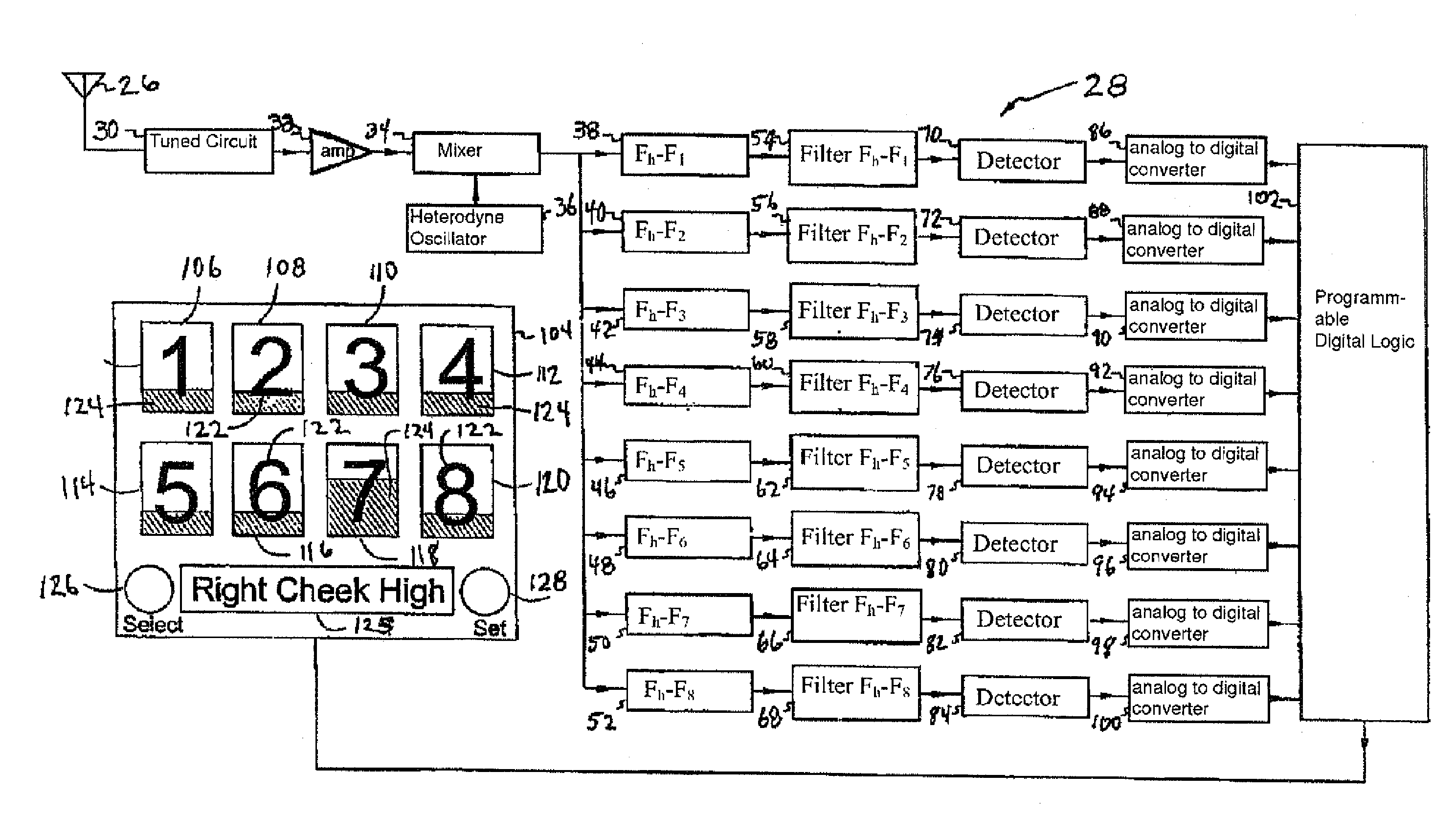
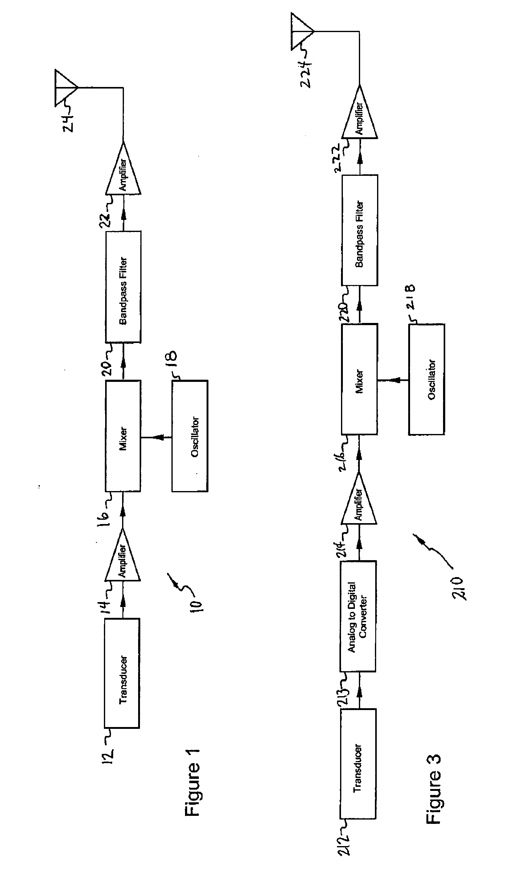
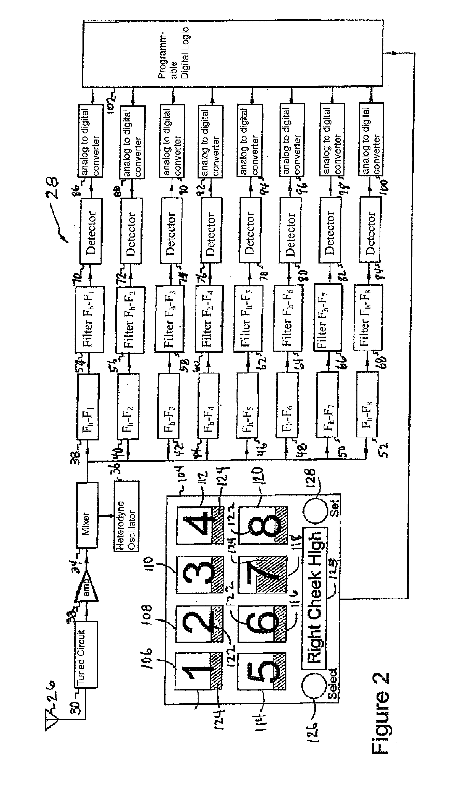
[0058]Referring to FIG. 1, a transmitter / transducer 10 constructed in accordance with the present invention and useful in the practice of the method of the present invention is illustrated. Transmitter / transducer 10 comprises a transducer 12, of conventional design, which is adapted to detect firing of a nerve and produce an electrical output proportional to the amplitude of such firing. The same may be a movement detector such as an inertial detector, and the computer to which its output is sent, as detailed below, may have software to prevent the detection of a benign movement as a twitch signaling the onset of nerve damage. Alternatively, any other type of detector, such as electrodes similar to those used in electrocardiogram systems, may be used.

[0059]Thus, each transducer / transmitter may operate at its own unique carrier signal frequency.

[0060]The output of transducer 12 it is sent to an amplifier which amplifies a signal and sends it to a mixer 16 which acts as a modulator. M...


PUM


Abstract

An apparatus for monitoring the activity of a surgeon. At least one wireless sensing unit is provided for monitoring potential damage to a nerve and is located at a first location of a body being operated on by a surgeon. The wireless sensing unit senses a change in the body at the first location resulting from potential damage to the nerve occurring at a second location of the body remote from the first location. The wireless sensing unit produces a wireless sensed change output signal indicative of the change in the body which is received by a receiver and generates a corresponding received output signal. An analyzer unit receives and analyzes the received output signal to determine the change in the body. An indicator responsive to the output of said analyzer unit indicates the change in the body to indicate the potential damage to the nerve the surgeon.

Description

RELATED APPLICATION[0001]This application is a non-provisional application based on and claiming the priority of U.S. patent application Ser. No. 11 / 854,967 filed Sep. 13, 2007 and directed to a System and Method for Facial Nerve Monitoring, which, in turn, claims the priority of provisional U.S. patent application Ser. No. 60 / 963,040.FIELD OF THE INVENTION[0002]The invention relates to the monitoring of nerve responses during surgery, and, in particular, the monitoring of facial nerves during surgery with the object of preventing permanent nerve damage.BACKGROUND[0003]In recent years, cosmetic surgery, and, in particular, cosmetic facial surgery is seeing dramatically increased use. This increase in the number of procedures performed each year is largely due to the fact that in the addition to the more elaborate and traditional face lift, other procedures, such as various versions of the S-lift are seeing widespread and increased performance. These procedures can be performed in on...

Claims


Application Information

Patent Timeline
Patent Type & Authority Applications(United States)
IPC IPC(8): A61B5/11A61B5/04A61B5/0488A61B5/145A61B5/00A61B5/053
CPCA61B5/0024A61B5/0488A61B5/1107A61B2505/05A61B5/4893A61B5/6814A61B5/742A61B5/1123A61B5/4041A61B5/389
Inventor COSTANTINO, PETER
Owner COSTANTINO PETER
Why Eureka
Try Eureka