Foot controller

a foot controller and foot technology, applied in the field of foot controllers, can solve the problems of non-ergonomically-optimal design of foot controllers, large size of foot controllers, and fatigue problems of performers, and achieve the effect of reducing manufacturing costs and increasing the degree of robustness and reliability

Inactive Publication Date: 2012-06-14
CICCONE MASSIMILIANO
View PDF0 Cites 49 Cited by
  • Summary
  • Abstract
  • Description
  • Claims
  • Application Information

AI Technical Summary

Benefits of technology

[0013]In a further embodiment, the first dielectric plate of the foot controller may advantageously be constituted by a printed circuit board, wherein said printed circuit board may further comprise a first metallic layer on which said two electrodes are etched. The external force applied to the sensor pad module may induce an elastic (i.e. reversible) deformation on the flexible circuit board, thereby modifying the geometry of the variable equivalent capacitor. In certain embodiments of the present invention, this construction may enable the realisation of a sensor pad module in which there are no hinged or rotatable moving parts and only the elastic deformation is responsible for the change in geometry of the variable capacitance. The foot controller thus obtained is characterised by an elevated degree of robustness and reliability. The mechanical simplicity of its construction makes it also particularly cheap to produce.
[0014]Further, the circuit board may comprise a second metallic layer connected to ground potential. The presence of this layer will prevent radiations from the capacitor on the sensor pad, since this is part of an oscillator circuit. This is advantageous when the foot controller is to be used in applications that are sensitive to electromagnetic (EM) disturbances, such as musical performances or in a medical environment.

Problems solved by technology

The fact that such switches are to be operated by foot is at the root of some of the well-known problems that users experience when operating a conventional foot controller.
In order to ensure a sturdy construction and to prevent involuntary operation, these foot-operable switches tend to be rather bulky and require a significant amount of physical effort by the user to operate them.
This leads to relatively large, non ergonomically-optimal design of said foot controllers, which, in turn, force the musician to perform ample movements with his / her leg and foot when operating the controller.
Additionally, a musician may be required to operate these switches a considerable number of times during the course of a musical performance, since it is common to switch sound presets many times during the one song, which may lead to fatigue problems for the performer, due to the physical effort involved.
Furthermore, these foot-operable push-button-type switches have a limited lifespan, due to the presence of moving mechanical parts, and to the fact that they are often operated in a harsh manner: due to the mechanical resistance encountered when switching, the user may tend to impart much more force than necessary to obtain the switching action, so as to ensure that the switching action is successful.
This manner of operating the switches clearly contributes to the limiting of their useful lifespan.
A further important problem inherent in foot controllers featuring foot-operable switches is the audible mechanical noise that the switches produce during the switching action.
This noise is easily picked up by neighbouring microphones (e.g. for voice recording) and negatively affects the quality of the recording.
In addition, the use of (foot-operable) push-button switches limits the number and variety of controls that can be imparted using a foot controller of this type.
It is therefore immediately clear that in order to expand the number of controlling actions one can perform with this type of controller, only two possibilities exist: the number of switches in the foot controller must increase, leading to an even larger and more difficult to operate controller (pressing the wrong switch during a live performance could have disruptive consequences for the continuity of the live musical act); or the user must repeatedly press the same switch to obtain the desired effect (for instance, he must press 10 times the same switch to increase the number of selected sound processing programmes by 10 units).
Both options are less than desirable and their drawbacks are readily appreciated.
Although U.S. Pat. No. 3,225,274 sought to tackle some of the problems mentioned above, the solution proposed is not suitable for the foot controller, which is the object of the present application.
The problem with the device in U.S. Pat. No. 3,225,274 is that it uses the operator's foot as dielectric between the two capacitor plates, thus making the whole controller's electrical response sensitive to the characteristic of the shoe and / or foot of the operator.

Method used


Image

  • Foot controller
  • Foot controller
  • Foot controller

Examples


Embodiment Construction

[0035]The foot controller and the method for generating control signals from the foot controller will be now described in detail with reference to the accompanying drawings. Wherever possible, the same reference numbers will be used throughout the drawings to refer to same or like parts, elements or operating steps.

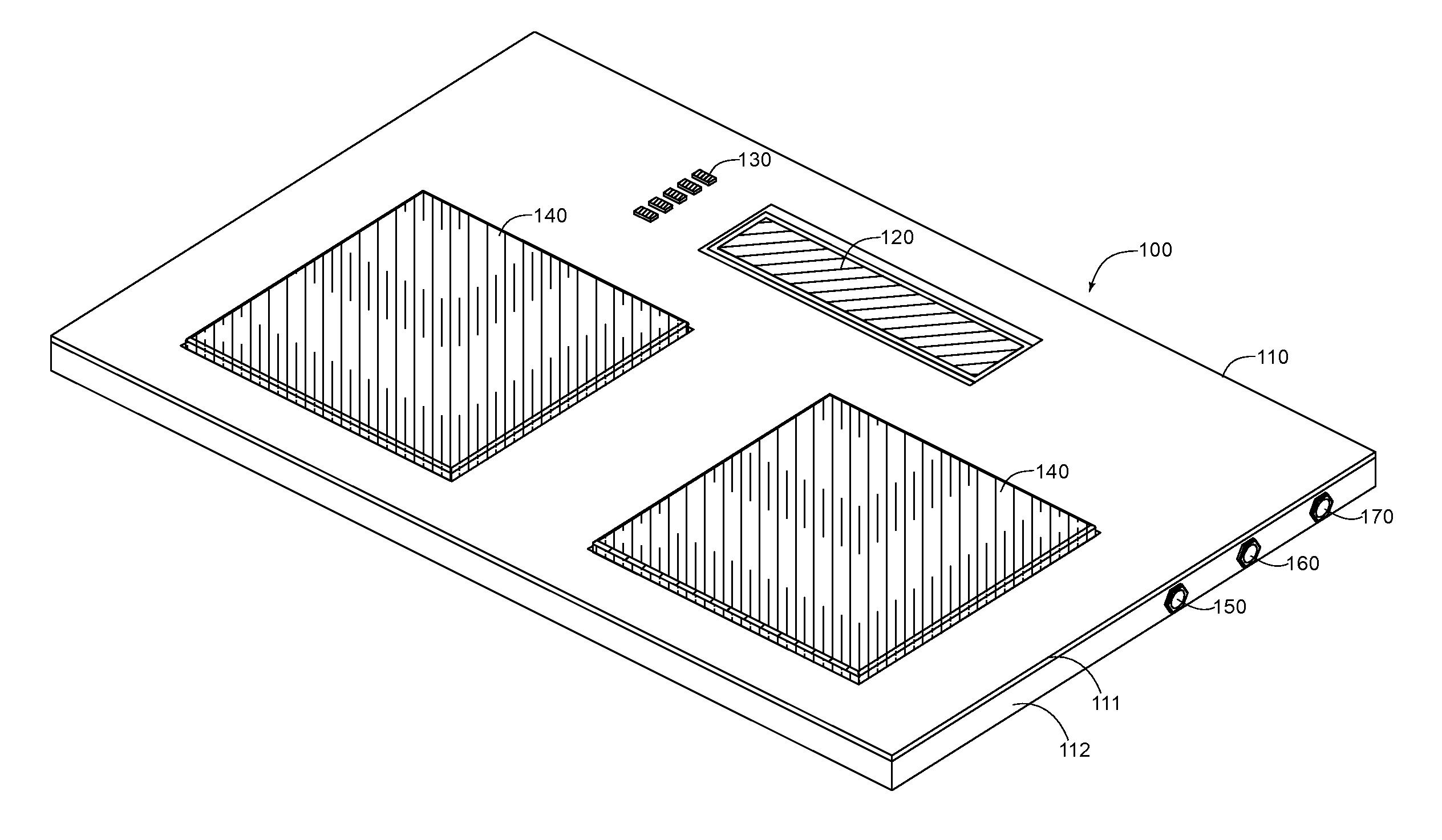
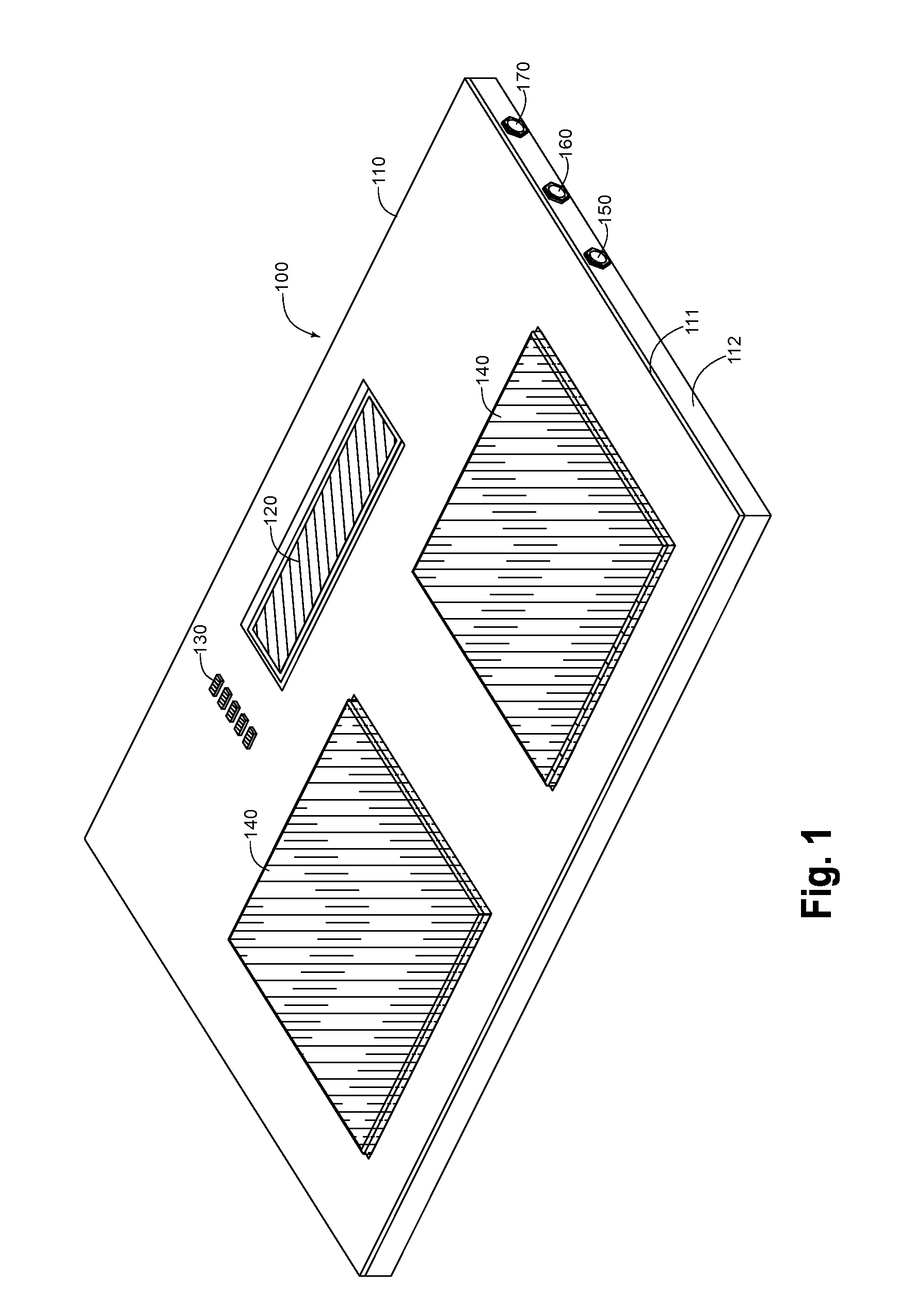
[0036]FIG. 1 shows a foot controller 100 according to an exemplary embodiment of the present invention. The controller may comprise a fixed housing 110. Housing 110 may comprise one or more elements, such as a top part 111 and a bottom part 112 connected to each other by means of screws or any other equivalent means, and may be constructed out of metallic, plastic or other materials. In an exemplary embodiment of the present invention the housing is made of steel. The skilled person will not have any difficulties in building the housing out of other materials such as aluminium, plastic, etc. The exemplary foot controller 100 may feature a number of connectors 150 to 170, ...


PUM


Abstract

A foot controller for electrically controlling a device by a user may include at least one sensor pad module having a first plate of dielectric material. The first plate of dielectric material may support at least two electrodes forming a planar capacitor. The controller may further include a second plate of dielectric material separated from the first plate by a layer of compressible dielectric material. The first plate is adapted to be displaced with respect to the second plate, so as to vary the geometry of an equivalent capacitor which includes the at least two electrodes, the compressible dielectric material and the second plate of dielectric material, thereby varying the value of the capacitance of the equivalent capacitor. The foot controller may further include a control module adapted to generate an electrical control signal which depends on the value of the capacitance.

Description

FIELD OF THE INVENTION[0001]The invention relates to a foot controller for generating control signals and to a method for generating control signals from a foot controller[0002]The invention may, in particular, be targeted to musicians needing to control musical instruments or sound processing devices, e.g. sound processors, amplifiers, sound effects, etc, while playing their instruments.BACKGROUND OF THE INVENTION[0003]Conventional foot controllers for use with devices such as sound processors, amplifiers, and other similar electronic devices feature a number of foot-operable switches—for instance of the push-button type (e.g. momentary or latching push-button switches)—through which a musician can switch on or off a certain feature of the sound processor being controlled, or increment or decrement by a fixed, non-adjustable quantity, a counter (controlling, for instance, a program or preset change). The fact that such switches are to be operated by foot is at the root of some of t...

Claims


Application Information

Patent Timeline
Patent Type & Authority Applications(United States)
IPC IPC(8): G10H1/32
CPCG10H1/344G01D5/2417
Inventor CICCONE, MASSIMILIANO
Owner CICCONE MASSIMILIANO
Why Eureka
Try Eureka