

Power cable with microduct
a micro-duct and power cable technology, applied in the direction of power cables including optical transmission elements, cables, insulation conductors/cables, etc., can solve the problems of fiber damage, no easy way to install such optical fiber cables,
- Summary
- Abstract
- Description
- Claims
- Application Information
AI Technical Summary
Benefits of technology
Problems solved by technology
Method used
Image

Examples
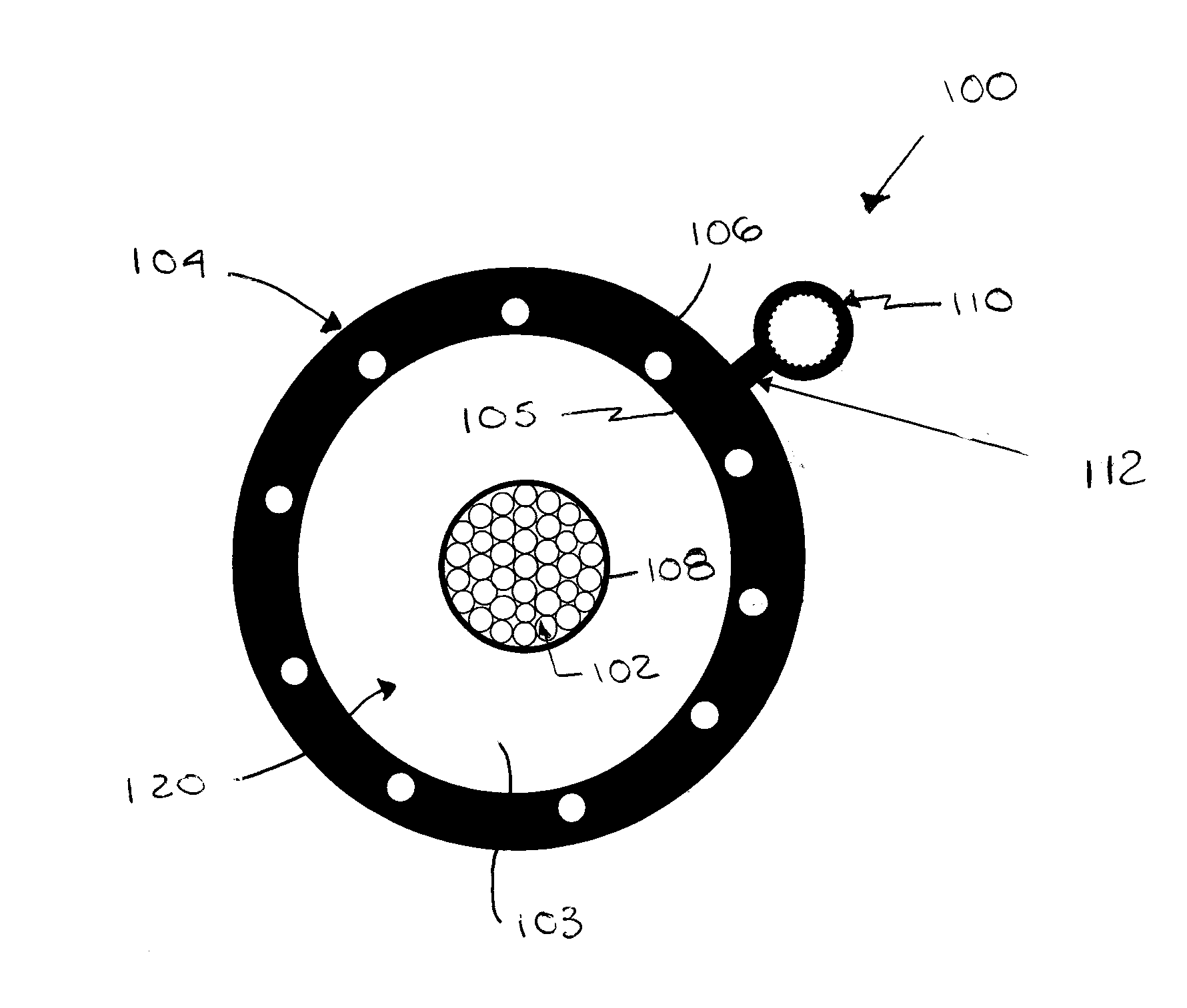
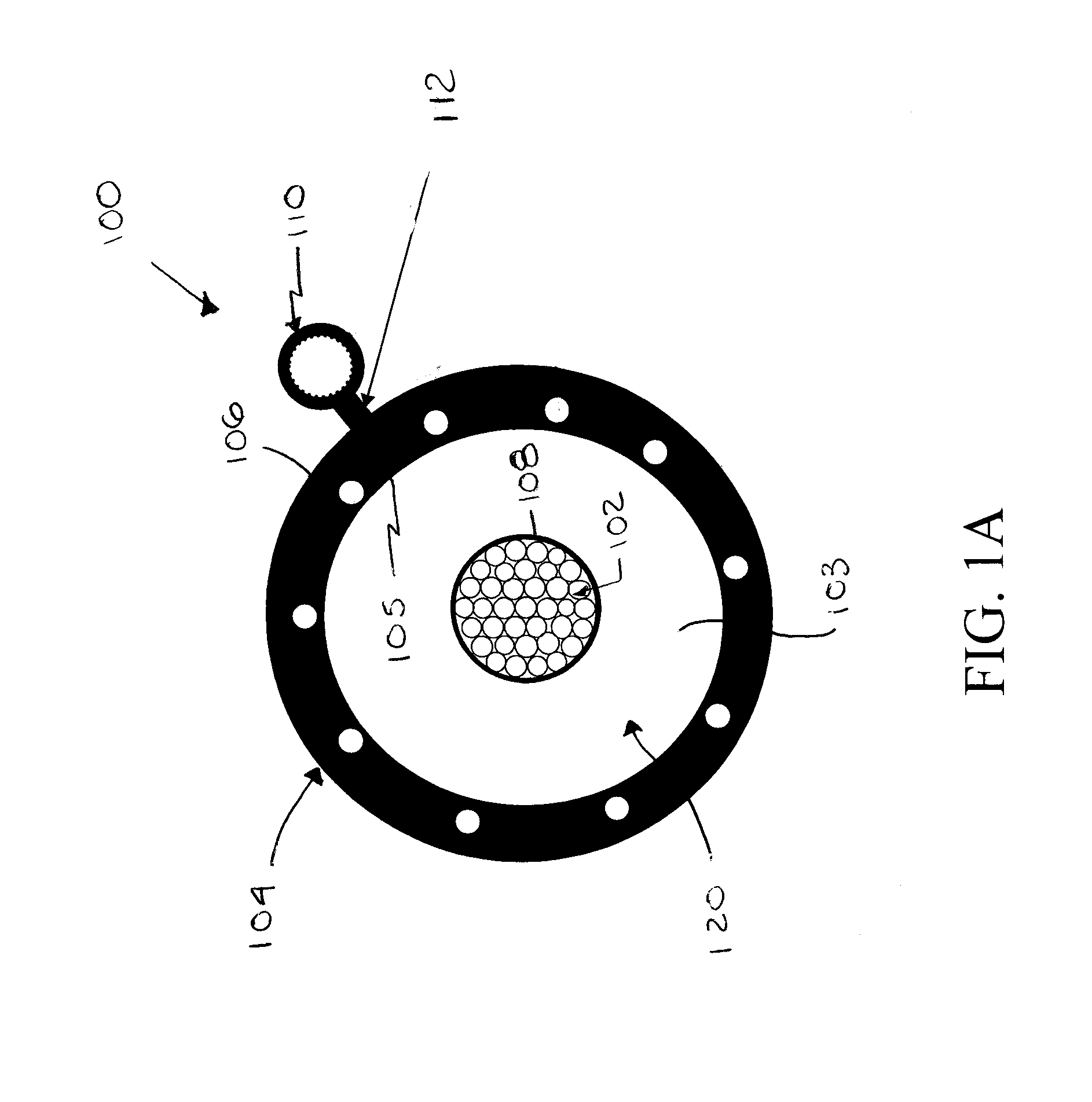
first embodiment
[0028]FIG. 2A illustrates a second exemplary embodiment of a power cable 200 according to the present invention. The power cable 200 is similar to the power cable 100 of the first embodiment, except that the microduct 210 is partially embedded in the outer surface 206 of the cable jacket 204. More specifically, a longitudinal recess 220 is formed in the jacket's outer surface 204 that is sized to receive at least a portion of the microduct 210. The microduct 210 is preferably held in place in the recess 220 with an adhesive, such as a double-sided tape, a hot melt adhesive, glue or the like. Alternatively, the recess 220 can be eliminated and the microduct 210 bonded to the outer surface 206 of the cable jacket 204.
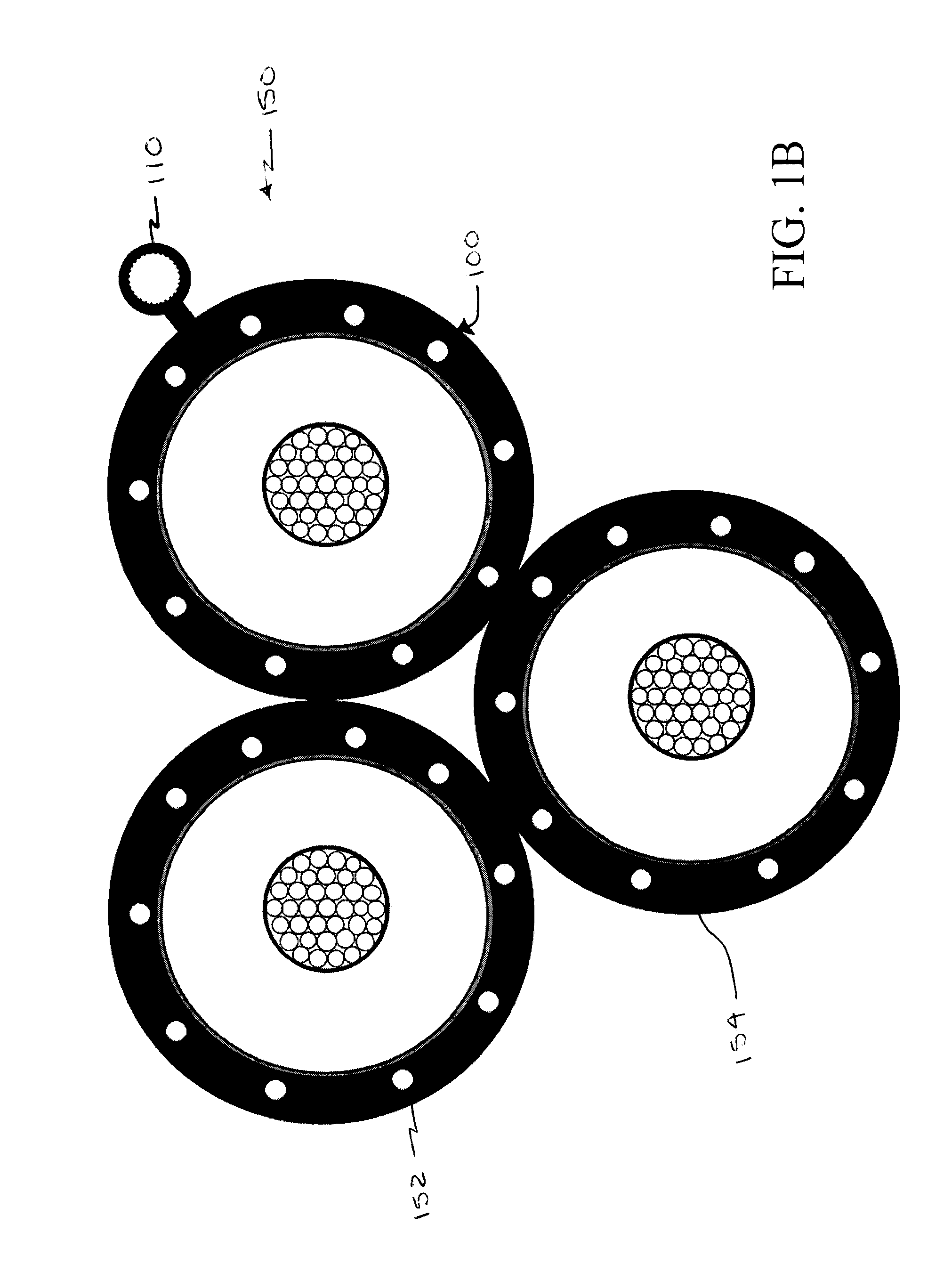
[0029]Similar to the first embodiment, the power cable 200 may be incorporated into a power cable assembly 250, as seen in FIG. 2B. The power cable assembly 250 includes a plurality of cables where at least one of the cables is the power cable 200 having the microduct 210...
fifth embodiment
[0035]FIG. 6 illustrates a sixth exemplary embodiment of the present invention of a power cable assembly 600 similar to the power cable assembly 500 of the fifth embodiment, except that a foam portion 650 is provided in the longitudinal area 620 between the first, second, and third power cables 602, 604 and 606. The foam portion 650 may have first, second and third arms 652, 654, and 656 extending to first, second, and third cables 602, 604, and 606, respectively. The foam portion 650 provides additional protection, e.g. crush resistance, to the microduct 610 between the cables. The foam material of the foam portion 650 preferably has a low thermal resistivity, such as foam containing thermally conductive ceramic particles or graphite.
[0036]FIG. 7 illustrates a seventh exemplary embodiment of the present invention of a power cable assembly 700 similar to the power cable assemblies 500 and 600, except that the foam portion 750 is wrapped around the microduct 710 like a longitudinal t...
PUM
 Abstract
Description
Claims
Application Information